Thanks bob. I still plan to model this circuit in LTSpice when I get time.Hi Stuart,
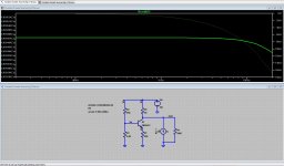
Q1: in this case the 20 refers to the output voltage, but it is also true that the CLG is very close to 20.
Q2: The attenuated output voltage would be 1.000V if the output voltage was exactly 20V, but the attenuated output voltage is ever so slightly less than that because the CLG is slightly less than 20. The attenuated output voltage will actually be 1.000V less 1.2mV, leaving 1.2mV to drive the input stage when the input voltage on the other side is 1.0V.
Cheers,
Bob
I am part way through chapters 19 - Spice Simulation. I have worked through from page 385 to 396.
I must say that your explanation and guidance through this chapter has been well written and easy to understand.
I have use LTSpice a few times in the past for very basic stuff.
I was so good to be introduced to some of the more advanced features.
I'm amazed that a program which has such a basic looking GUI has all these features and functions available.
I did however run into trouble with the THD calculation. I believe that I have following your instructions in the book but ultimately I end up with a THD value of 74.5% were I should be getting 0.035%
Any Ideas were I could be going wrong?
As I look forward to continuing this chapter.
Sent from my SM-G920I using Tapatalk
Hi Bob, After downloading your sample models. (which are awesome and so handy  ) I noticed that there was a difference between the SPICE directive that was in the book on page 396 and your actual model. As in the line in the book says;
[book=
Add the SPICE directive .four 1-kHz 10 8 V(Vout) to the differential pair schematic.
]%[/book]
But the actual sample file Figure 19_1 ->> Distortion ->> Demonstration circuit
The SPICE directive is .four 1khz 10 4 v(vout)
It was the 1-khz and the little negative sign copied from the book that I discovered was giving me the incorrect results. (rookie mistake I guess )
)
I understand that the 8 & 4 are different too, but this from what I understand is just asking SPICE to process the FFT processing to with the last 8 or 4 ms of data. I thinks from what I understand that it also has an effect on the frequency resolution and number of spectral lines generated.
) I noticed that there was a difference between the SPICE directive that was in the book on page 396 and your actual model. As in the line in the book says;[book=
Add the SPICE directive .four 1-kHz 10 8 V(Vout) to the differential pair schematic.
]%[/book]
But the actual sample file Figure 19_1 ->> Distortion ->> Demonstration circuit
The SPICE directive is .four 1khz 10 4 v(vout)
It was the 1-khz and the little negative sign copied from the book that I discovered was giving me the incorrect results. (rookie mistake I guess
)I understand that the 8 & 4 are different too, but this from what I understand is just asking SPICE to process the FFT processing to with the last 8 or 4 ms of data. I thinks from what I understand that it also has an effect on the frequency resolution and number of spectral lines generated.
Hi Jan, thanks for your interest. I have given up on the sim I was using and spent a quite some time going through chapter 19. It was time well spent. That LTSpice software is an amazing tool and thanks to the great explications by bob in his book I feel like I can navigate my way around the software. However I am sure I will go over the chapter a few more time before I am feeling confident on how to use it on my own.Your CL gain should be very close to 20 anyway; is it?
Jan

output impedance
Hi bob,
I was trying to model the output impedance of your current sources as per models 2.10a - etc.
I ran into trouble trying to get the values correct.
I spotted the post below which explained to some degree why I could not get my answers to correlate.
http://www.diyaudio.com/forums/solid-state/232477-computing-output-impedance-cordells-book.html
If you could, I would really appreciate it, if you could post an example of how to model the output impedance as you did in the book in LTSpice. So I can and other forum users can in the future use it to compare circuits.
I have attached a sample of 2.10a and how I was trying to measure output impedance if that helps.
From what the book says on page 37 the output impedance should be about 290K
Attachments
IPS & VAS - Current source questions
Hi all.
I see in bob's book for the example amplifier that he uses 2mA for the IPS tail current to the differential amplifier and 10mA to feed the VAS.
Can anyone please tell me how these number are derived.
Is it just the best value based on the Q point of the transistor and its operating range based on a input signal of that will range from 0v to 1v?
If its in bob book please help me with a page number or some other reference.
Thanks
to measure ccs output Z you need to remove the effect of R5 which is small signal AC grounded by being connected to the Vin Voltage source
the easiest, practical way to measure ccs/I source output Z is with a V source instead of your I1
in Spice however you can "do it the hard way ", extract the data you want from "unreasonable" setups
Ic(Q1) is a valid waveform, as is V(Zout); together V(Zout)/Ic(Q1) should display the small signal AC collector Z of the ccs - you may have to change the waveform display to linear to get the reading in (complex) Ohms
Hi all.
I see in bob's book for the example amplifier that he uses 2mA for the IPS tail current to the differential amplifier and 10mA to feed the VAS.
Can anyone please tell me how these number are derived.
Is it just the best value based on the Q point of the transistor and its operating range based on a input signal of that will range from 0v to 1v?
If its in bob book please help me with a page number or some other reference.
Thanks
Hi Stuart,
The IPS tail current and the VAS bias current are chosen by judgment and they are not sacred. There is actually a fairly wide range of acceptable values for each. However, I will be the first to admit that those numbers of 2mA and 10mA may not be the absolute optimum values.
If the IPS tail current is too small, input stage gm will go uncomfortably low, input voltage noise may rise, and current available to charge and discharge the Miller compensation capacitor may be too small and limit slew rate. These issues are also tied in with the amount of degeneration chosen for the IPS (I usually go with 10:1 degeneration, but that is also a bit arbitrary). If the tail current is too high, input current noise will rise, gm will go up and that may necessitate a larger Miller capacitor that in turn may load the VAS output node more than desirable. I am most comfortable with a Miller capacitor value that lies between about 15pF and 100pF. Too high an IPS tail current will also exacerbate amplifier offset voltage issues due to higher IPS input bias current.
If the VAS bias current is too small, the VAS' ability to drive the output stage will be compromised (especially if the output stage is only a double) and the available slew rate at the VAS output node will be limited. If the VAS bias current is too high, VAS dissipation will go up and VAS output impedance will go down. High VAS bias current may be a greater problem in designs that do not use a Darlington-like arrangement (2T VAS).
There are numerous interacting considerations in choosing these currents and there is no exact answer. It is a judgment call subject to tweaking.
Cheers,
Bob
Thank you, for taking the time to explain all that Bob.
That was a really clear explanation that you gave. It was especially helpful because you gave both cases for the IPS / VAS and the consequences for to much or to little current.
I will read it over a few more time and review it with the information in chapter 3.
Thanks again.
That was a really clear explanation that you gave. It was especially helpful because you gave both cases for the IPS / VAS and the consequences for to much or to little current.
I will read it over a few more time and review it with the information in chapter 3.
Thanks again.
to measure ccs output Z you need to remove the effect of R5 which is small signal AC grounded by being connected to the Vin Voltage source
the easiest, practical way to measure ccs/I source output Z is with a V source instead of your I1
in Spice however you can "do it the hard way ", extract the data you want from "unreasonable" setups
Ic(Q1) is a valid waveform, as is V(Zout); together V(Zout)/Ic(Q1) should display the small signal AC collector Z of the ccs - you may have to change the waveform display to linear to get the reading in (complex) Ohms
Thanks for your input jcx. Is there any chance you could post a LTSpice Schematic file as a sample. I was trying to model 2.10a, b or c
thanks
2N5551 considered harmful if operated at 10mA: (link)
Hi Mark,
Thanks for running the quasi-saturation curves for the numerous transistors at the link. I would not use the term "harmful" to describe operating the 2N5551 at 10mA as long as it was within its rated dissipation. Quasi-saturation is certainly a shortcoming of an imperfect transistor.
We are always searching for better transistors for any given location in an audio amplifier. An example of where the 2N5551 might be used at 10mA might be the VAS or a pre-driver. These locations in an amplifier generally require a transistor with a rated voltage greater than 120V, since they have to withstand twice the rail voltage. High voltage transistors typically have more quasi-saturation effects at low voltage for a given amount of current as compared to transistors with only 40-60V breakdown. Most of the transistors that exhibited good quasi-saturation behavior in your tests were rated at less than about 60V.
A nice transistor for the VAS or predriver is the 2SC3503, with 300V breakdown and 150MHz ft. However, its curves also exhibit quasi-saturation.
I'm very interested in knowing of VAS/predriver transistors that are better than the 2SC3503. It would be nice to have one with a breakdown of >150V, ft > 150 MHz, small Cbc, and minimal amount of quasi-saturation at 10mA.
Thanks again for this data.
Cheers,
Bob
Thanks Bob. One possible workaround is to run cascoded stages at higher power supply voltage than the output stage. Then, even at clipping, there's plenty of VCE across the transistors in the cascode. I recall that you do this already, via extra turns manually wound on the toroidal power transformer, to overcome the large Vgs_ON of the MOSFET source follower output transistors. So the simplest no-brainer tweak is to just wind more turns, and keep using your same transistor types that quasi saturate.
Thanks Bob. One possible workaround is to run cascoded stages at higher power supply voltage than the output stage. Then, even at clipping, there's plenty of VCE across the transistors in the cascode. I recall that you do this already, via extra turns manually wound on the toroidal power transformer, to overcome the large Vgs_ON of the MOSFET source follower output transistors. So the simplest no-brainer tweak is to just wind more turns, and keep using your same transistor types that quasi saturate.
Hi Mark,
I agree; I like boosted rails for the VAS and IPS, and maybe the predriver, especially for MOSFET amplifiers. The boosted rails also make it easier and less consumptive of headroom to implement Baker clamps. It is also easier to make the boosted rails quite clean because the currents are lower and a couple of volts can be allowed to be used in the filtering. Of course, boosted rails also make room for a capacitance multiplier. I used boosted rails in my MOSFET power amplifier with error correction.
Of course, boosted rails add to the cost of the power supply, usually requiring extra windings on the power transformer or an additional low-voltage dual secondary transformer whose windings sit atop the main transformer's windings to drive a separate rectifier - reservoir capacitor arrangement (reservoir capacitors can be much smaller). I often implement the extra windings for boosted supplies by hand-winding a number of turns on a toroid power transformer. Depending on the transformer, you often get something on the order of 0.7 volts ac per turn.
A useful, but less effective, compromise is to just use a separate rectifier - reservoir capacitor arrangement fed by the regular AC windings. This supply will be easier to filter and will not tend to have large ripple and sag as a result of the output stage under high-power conditions (which is when the VAS needs to swing a lot).
Cheers,
Bob
Transistors wanted
As some of you know, I'm working on the second edition of my book. One of the things I'd like to do is to expand and bring up to date some of the transistors I am discussing. In perticular, I want really good transistors that can still be purchased.
Here are the kinds of your favorite candidates I want you to suggest:
1. Good IPS transistors in TO-92 packages that can handle at least 70V, have ft > 100 MHz, and have beta >100.
2. Good VAS and predriver transistors, likely in TO-126 packages, that can handle at least 130V, have ft > 100 MHz, and have beta > 100. The 2SC3503 meets these requirements, but I am interested in knowing of others, since availability of good discrete transistors can be spotty.
3. Good driver transistors, likely in TO-220 packages that have similar capabilities to those above, but with higher dissipation and SOA capability.
4. Good power transistors, likely in TO-247, TO-264 and MT-200 packages that have characteristics similar to, or better than, the MJL3281 and MJL1302.
Cheers,
Bob
This is what I have on stock and most parts are still available.
IPS transistors
VAS and predriver transistors
Driver transistors
Power transistors / L-MOSFET
Power transistors / V-MOSFET
Best regards,
Toni
P.S.: really hard waiting for the second edition of your book
IPS transistors
- 2N3904TAR / 2N3906TAR (40V)
- BC550C / BC560C (50V)
- KSC1815 / KSA1015 (50V)
- BC327-40 / BC337-40 (40V)
- KSC1845 / KSA992 (120V)
VAS and predriver transistors
- KSC3503D / KSA1381E
- KSC2690AYS / KSA1220AYS (160V, high cob)
- 2SC3902T / 2SA1507T (160V)
Driver transistors
- KSC2690AYS / KSA1220AYS (160V, high cob)
- 2SC3902T / 2SA1507T (160V)
- 2SC4793 / 2SA1837 (Toshiba/obsolete but available)
- 2SC4793LB-TF3T / 2SA1837LB-TF3T (UNISONIC)
- 2SC6145A / 2SA2223A
- 2SC6145AY / 2SA2223AY
- TTC5200 / TTA1943
- MG6330 / MG9410
- MG6330-R / MG9410-R
Power transistors / L-MOSFET
- ECX10N20/ECX10P20
- ECW20N20/ECW20P20
- IRF610/IRF9610
Power transistors / V-MOSFET
- IRF640/IRF9640
- IRFP240/IRFP9240
Best regards,
Toni
P.S.: really hard waiting for the second edition of your book
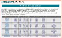
Have you looked at Profusions website as they list quite a lot of audio oriented transistors. A couple of links here but its worth a browse of the site.
Medium Power-Driver | Profusion Audio Design
Scroll down:
Sanken Audio Components Guide
And an old picture chart of mine.
Medium Power-Driver | Profusion Audio Design
Scroll down:
Sanken Audio Components Guide
And an old picture chart of mine.
Attachments
This is what I have on stock and most parts are still available.
IPS transistors
- 2N3904TAR / 2N3906TAR (40V)
- BC550C / BC560C (50V)
- KSC1815 / KSA1015 (50V)
- BC327-40 / BC337-40 (40V)
- KSC1845 / KSA992 (120V)
VAS and predriver transistors
- KSC3503D / KSA1381E
- KSC2690AYS / KSA1220AYS (160V, high cob)
- 2SC3902T / 2SA1507T (160V)
Driver transistors
Power transistors / BJT
- KSC2690AYS / KSA1220AYS (160V, high cob)
- 2SC3902T / 2SA1507T (160V)
- 2SC4793 / 2SA1837 (Toshiba/obsolete but available)
- 2SC4793LB-TF3T / 2SA1837LB-TF3T (UNISONIC)
- 2SC6145A / 2SA2223A
- 2SC6145AY / 2SA2223AY
- TTC5200 / TTA1943
- MG6330 / MG9410
- MG6330-R / MG9410-R
Power transistors / L-MOSFET
Medium power transistors / V-MOSFET
- ECX10N20/ECX10P20
- ECW20N20/ECW20P20
- IRF610/IRF9610
Power transistors / V-MOSFET
- IRF640/IRF9640
- IRFP240/IRFP9240
Best regards,
Toni
P.S.: really hard waiting for the second edition of your book
Hi ASTX,
Thanks very much for putting this list of transistors together. I'll take a peek at the datasheet and availability on each one of them.
Cheers,
Bob
Have you looked at Profusions website as they list quite a lot of audio oriented transistors. A couple of links here but its worth a browse of the site.
Medium Power-Driver | Profusion Audio Design
Scroll down:
Sanken Audio Components Guide
And an old picture chart of mine.
Hi Mooly,
Thanks for this information. I appreciate it.
Cheers,
Bob
Hi ASTX,
Thanks very much for putting this list of transistors together. I'll take a peek at the datasheet and availability on each one of them.
Cheers,
Bob
You are welcome!
Medium power driver transistors:
- 2SC4883A / 2SA1859A (180V, Cob ~30pF, Sanken, TO220)
- 2SC4027T / 2SA1552T (160V, Cob 12/22pF, Onsemi, TO251, SMD style with through hole, but can be mounted using steel spring or something else)
Medium power driver transistors:
...
2SC4027T / 2SA1552T (160V, Cob 12/22pF, Onsemi, TO251, SMD style with through hole, but can be mounted using steel spring or something else)
Interesting to see someone mention these devices.
I have 2SA2205 & C6099 (actually a hFE mismatch) mounted as SMD doing driver duty in a CFP arrangement. Despite being lower voltage (100V) there isn't much of a SOA deficiency in the areas of interest. Conveniently their SOA just about matches the needs of 1 pair TTA1943/C5200 or TTA0002/C0002 (for 4 ohm) at approx 37V rails.
NXP's LFPAK double transistors (PHPT61*) also raise interesting possibilities for the adventurous (but of course Bob's asked for through hole devices!)
Last edited:
- Home
- Amplifiers
- Solid State
- Bob Cordell's Power amplifier book