I have a question about the Re discussion:
I've noticed that in some older (power-) amplifiers for Re values of .5 Ohms to 1 Ohm are applied. Is there a special business-case for making such choises?
Simulating such an amp with Re = .22 or .10 seemed to work too, with even lower distortion. From what has been discussed here already, I would not consider using the .10 Ohms in real life, since the output-stage has no protection against exceeding SOA.
I suspect some design issue that's solved by using higher values for Re. Can somebody tell me if that assumption is correct and if not, why?
Thanks in advance.
Edwin
Not all amplifiers out there follow the Oliver criteria. This can be intentional or out of ignorance. Higher RE can sometimes let you get away with less expensive thermal design without thermal runaway.
Some of this is just experience, some is based on what individual designers like the most or fear the most. The general consensus here is to use about 0.22 ohms and bias the amplifier at approximately the Oliver criteria.
Cheers,
Bob
I learned a lot about the Re. At this point, I think I am more comfortable to go below 0.22. I think if you match the Vbe and beta closely between the parallel transistors, you can definitely go lower than 0.22.
The equation 15.2 in p300 of Mr.Cordell's book is for calculation of a single transistor, which, assuming that transistor is hogging all the current. If you spread it out between parallel transistor, it's a lot better.
Key thing is the rail voltage, there is no other way around it unless you do something very special to lower the thermal resistance. So matching transistors is the alternative way.
At this point, I am tending to go with 0.15 or 0.18ohm resistor instead of 0.12 originally designed. I have 5 pairs, I matched the transistor to 1% easily and I use 40V rail, it's a lot more forgiving. I am going a lot more conservative than Self.
So as of now, it's 0.15ohm, at 175mA, dissipating 70W per channel at idle. Or,
0.18ohm, 150mA dissipating 58W per channel.
Both satisfy Oliver's condition.
Alan,
Let me be blunt. As a relative beginner with little experience, it would be foolish for you to go below 0.22 ohms for RE. It is simply not worth it.
My equation 15.2 does apply to providing insight for current hogging among multiple output pairs, but I probably could have done a better job of explaining its relevance to multiple output pairs.
Cheers,
Bob
A ferrite bead can be thought of as a very lossy inductor, but the loss is not series resistance, it is loss introduced by the ferrite. The impedance starts out very low, nearly zero, at dc, then at high frequencies it increases, somewhat like that of an inductor, then it levels off at very high frequencies, where it looks resistive. It can be roughly approximated by a small inductor in parallel with a resistor.
Cheers,
Bob
I'm asking because I'm wondering why we don't just use a small air core inductor with a resistor for base. This would be much more linear.
I am not sure how to interpret that DC current vs Z impedance data. But it looks to me that 0.5A of DC has reduced the HF impedance by less than half at the most affected HF frequencies.Just as a random example, see this data sheet for some 1 A and 3 A rated ferrites. Look at figures xxB on the second page to see how the impedance varies with DC bias current.
http://www.farnell.com/datasheets/327249.pdf
Ferrite has a low saturation flux density of typically 300 mT or less. Coupled with high µr, it is easy to saturate.
For a paralleled output stage, a base current of 0.5Apk indicates at least 20Apk of output current from a 2pair stage (hFE = 20 @ Ic = 10Apk).
A 3pr to 5pr output stage should have massively lower peak base currents into the rare transients that result in output approaching 15Apk to 20Apk.
That prompts me to ask.
Does a drop in ferrite bead HF impedance of at worst case 50% of the no DC condition, have any consequence when used as a base stopper?
Last edited:
Hi Doug,
In my chapter 14.6 I discuss local thermal stability at length, with focus on Fig. 14.15 and Eq. 15.2. I describe local thermal stability as the case where the heat sink is not in the equation - it is considered infinite. I think this is the best you can do in principle with thermal bias stability.
With Eq. 15.2 there is considerable discussion and sanity check examples as described in Eqs 15.3 - 15.6. Can you tell me what it is about the material in chapter 14.6 that you disagree with, particularly Figure 14.15 and Eq. 15.2. If there is an error, or there needs to be some added caveats, or examples of mitigating circumstances, I want to improve the treatment in my second edition.
Cheers,
Bob
Certainly. On p300 you say "It is assumed... that there is no temperature-compensating effect in the bias-spreader" (What I call the bias generator)
And there's the issue- on all my EF amplifiers the temperature on the top of an output device is sensed, not the main heatsink temperature. This gives an admittedly imperfect feedback path from the transistor junction to the temp sensor, but it is much better than any attempt to use the main heatsink.and in my experience (up to 6 output pairs) this gives excellent stability and no sign at all of runaway. It is easy to do with plastic devices. It also works well with TO-3, though the mechanics are more complicated.
I usually only sense one output device, though with more circuitry you could sense every one and derive an aggregate bias figure. One could contemplate the effect of Re tolerances (they are usually 5% parts) but as I say, all my practical experience tells me that there is not a problem.
I have been recommending the top sensor method for some 20 years now.
I would also point out that you have neglected the resistance of the emitter lead, emitter bond wire, etc. I don't have figures here but I suspect they are significant compared with 0R1 Re's.
BTW, I'm not clear why the equations in Chapter 14 are labelled 15.**.
Not all amplifiers out there follow the Oliver criteria. This can be intentional or out of ignorance. Higher RE can sometimes let you get away with less expensive thermal design without thermal runaway.
Some of this is just experience, some is based on what individual designers like the most or fear the most. The general consensus here is to use about 0.22 ohms and bias the amplifier at approximately the Oliver criteria.
Cheers,
Bob
Thanks for explaining, Bob.. very usefull, since the "radiator" of this amp is a piece of Aluminium approx. 23x35 cms...
So that might be the reason...
I'm asking because I'm wondering why we don't just use a small air core inductor with a resistor for base. This would be much more linear.
I suspect that this would be fine; I think I mentioned it in passing in a post earlier. Just wind as many turns will fit around a 10-ohm half watt TH resistor. Try #30 wire. The winding can probably be pretty sloppy.
Cheers,
Bob
And there's the issue- on all my EF amplifiers the temperature on the top of an output device is sensed, not the main heatsink temperature. This gives an admittedly imperfect feedback path from the transistor junction to the temp sensor, but it is much better than any attempt to use the main heatsink.and in my experience (up to 6 output pairs) this gives excellent stability and no sign at all of runaway. It is easy to do with plastic devices. It also works well with TO-3, though the mechanics are more complicated.
I have been recommending the top sensor method for some 20 years now.
By top sensor, Do you mean the bias spreader transistor is BOLTED on top of the power transistor?
This is exactly what I did on my layout. I saw a lot of the amp have the spreader bolted just on the heatsink, I was thinking that's not very good and slow to response. I use TO-264 plastic package, I just bolt the KSC3503 right on top with grease. I was guessing even though it's on the plastic, it should still be a lot faster in response and closer to the real temperature of the power transistor.
Layout is everything, I spent a lot of time on the layout. Use 3EF diamond and I have the NPN pre-driver bolted with the PNP big driver on a separate heatsink to so they track and cancel out. The bias spreader ONLY has to temperature compensate the big power transistors. I think I should get the fastest and closest thermal tracking and response it can be.
Certainly. On p300 you say "It is assumed... that there is no temperature-compensating effect in the bias-spreader" (What I call the bias generator)
And there's the issue- on all my EF amplifiers the temperature on the top of an output device is sensed, not the main heatsink temperature. This gives an admittedly imperfect feedback path from the transistor junction to the temp sensor, but it is much better than any attempt to use the main heatsink.and in my experience (up to 6 output pairs) this gives excellent stability and no sign at all of runaway. It is easy to do with plastic devices. It also works well with TO-3, though the mechanics are more complicated.
I usually only sense one output device, though with more circuitry you could sense every one and derive an aggregate bias figure. One could contemplate the effect of Re tolerances (they are usually 5% parts) but as I say, all my practical experience tells me that there is not a problem.
I have been recommending the top sensor method for some 20 years now.
I would also point out that you have neglected the resistance of the emitter lead, emitter bond wire, etc. I don't have figures here but I suspect they are significant compared with 0R1 Re's.
BTW, I'm not clear why the equations in Chapter 14 are labelled 15.**.
Hi Doug,
Yes, I've always thought the idea of putting the sensing transistor on top of one of the power transistors was a good idea, and it makes sense that this would help. I'll add a discussion of that in my second edition and give you due credit. Is there anyone else that I should also credit in that regard?
Sort of half way between using the heat sink and using a ThermalTrak.
I don't have your book in front of me, but where you recommend the use of 0.1 RE, do you there mention the caveat that this should only be done if the sensing transistor is mounted atop one of the output transistors?
Yes, in that simplified equation the ohmic component of the emitter resistance (and base/base stopper resistance divided by beta) was omitted as an example of a worst-case scenario. However, as the ohmic portion of the impedance seen looking into the emitter gets close to RE, lots of assumptions about RE and the Oliver criteria break down. As I pointed out elsewhere in my book, that ohmic component should be included as part of RE in calculating the proper bias current to fulfill the Oliver criteria. Even with 0.22 RE this effect can be seen in that the voltage across the external RE may have to be a bit smaller than 26mV.
Do you still bias to 26mV across the 0.1 RE? If so, how do you justify that in light of the ohmic component of emitter resistance I just described?
I do understand that your not using a base stopper resistor mitigates this "error" a little bit (a 4.7 ohm base stopper with a beta of 100 would look like about 0.05 ohm) - or the converse.
The equations in chapter 14 are numbered as 15.xx because I screwed up
") .
.Cheers,
Bob
Alan,
Let me be blunt. As a relative beginner with little experience, it would be foolish for you to go below 0.22 ohms for RE. It is simply not worth it.
My equation 15.2 does apply to providing insight for current hogging among multiple output pairs, but I probably could have done a better job of explaining its relevance to multiple output pairs.
Cheers,
Bob
Point taken, I was also thinking the comments from Ostripper and others that they feel the sound open up on higher rail voltages. That I have to lower the bias current and raise the Re to meet Oliver's condition. Is there any truth about higher rail voltage give better sound? If so, why?
I read p300 and 301 many times, you specifically said this is for a single transistor. If you look at equation 15.2, the gm calculation is for single transistor and so is the thermal resistance 1.1deg/W is for a single transistor. So I assume you meant this is the worst case in hogging that one transistor hog up all the current. That if the parallel transistors are sharing current, it is going to be a lot more forgiving.
Thanks
Hi Doug,
Yes, I've always thought the idea of putting the sensing transistor on top of one of the power transistors was a good idea, and it makes sense that this would help. I'll add a discussion of that in my second edition and give you due credit. Is there anyone else that I should also credit in that regard?
Ha ha, it's 20 years late from Self, but I did post drawings and pictures in #5602 and #5604 in this thread that I layout to bolt the bias spreader KSC3503 on top of the big TO-264 power transistor. #5602 have the drawing showing that. #5604 show how I have the NPN pre-driver bolted with the PNP driver together on a separate heatsink.http://www.diyaudio.com/forums/solid-state/171159-bob-cordells-power-amplifier-book-561.html
Don't worry about credit, I just thought it's common sense that you cannot track faster and closer than right on top. I don't like the thermal track as it's only a diode and you can only use one of them, it's not much better.
Last edited:
http://www.paco-electronics.com/pdf/Chemical%20Composition%20of%20Transistor%20products%20%28Lead%20Free%29.pdf
The doped epoxy case molding of most output semi's has a inferior thermal
conductivity. The (plastic) to-126's layer near the die is extremely
thin , not as big a problem.
Member Bonsai's approach of attaching the sensor to the collector lead
might be the closest to a real thermal-trak.
And for an EF3 , having the secondary dynamic sensor on the drivers is the
#2 best approach (below 1).
I've even had the privilege to test and observe the very best (below 2).
Nothing short of amazing thermal stability , here !! It's even immune to
VAS current fluctuations. I am just scared to use the NJL , as ON might
discontinue it ... Sanken also has a similar on-die sensor output , but
it would need to be matched with similar sanken outputs.
I suppose , for a hobbyist (and an EF2) , Doug's way is best.
Overload and thermal stability are quite important first steps , we can
always design uber low THD in after (it has to survive).
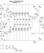
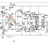
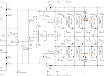
PS - Alan - #2 pix is one of the most expensive , highly reviewed "badest" amps out there ...
Note what they are using for Re !
OS
The doped epoxy case molding of most output semi's has a inferior thermal
conductivity. The (plastic) to-126's layer near the die is extremely
thin , not as big a problem.
Member Bonsai's approach of attaching the sensor to the collector lead
might be the closest to a real thermal-trak.
And for an EF3 , having the secondary dynamic sensor on the drivers is the
#2 best approach (below 1).
I've even had the privilege to test and observe the very best (below 2).
Nothing short of amazing thermal stability , here !!
It's even immune toVAS current fluctuations. I am just scared to use the NJL , as ON might
discontinue it ... Sanken also has a similar on-die sensor output , but
it would need to be matched with similar sanken outputs.
I suppose , for a hobbyist (and an EF2) , Doug's way is best.
Overload and thermal stability are quite important first steps , we can
always design uber low THD in after (it has to survive
).PS - Alan - #2 pix is one of the most expensive , highly reviewed "badest" amps out there ...
Note what they are using for Re !
OS
Attachments
Last edited:
Member Bonsai's approach of attaching the sensor to the collector lead
might be the closest to a real thermal-trak.
OS
I saw that too, I decide not to follow because the lead of the transistor is at least 3/8 to 1/2" long, being good heat conductor, it will loose heat along the lead length and temperature drop along the lead. That's the reason I went with bolting on top in my design.
Used case top vbe sensing on Infinity IRS servo amp in early 1980s, on many projects later including PS Audio 100 Delta and 250 Delta. Similar performance to thermal trak before they were available. Built an amp with Sanken darlingtons with internal vbe elements in 2001 that used no emitter resistors, bypassed the internal resistors that were weaker than the transistors.
I saw that too, I decide not to follow because the lead of the transistor is at least 3/8 to 1/2" long, being good heat conductor, it will loose heat along the lead length and temperature drop along the lead. That's the reason I went with bolting on top in my design.
Loss is not the issue , speed is. Metal is quicker than epoxy - period.
OS
Beware !
The semi epoxy flame retardant , Antimony Trioxide - is a powerful
carcinogen.
So .. the "magic smoke" might give you cancer.
Carbon black seems to be the only enhancement of thermal conductivity.
Some "special" plastic carbon additives can be at >40w/mk, same chart
for copper is >400.
OS
The semi epoxy flame retardant , Antimony Trioxide - is a powerful
carcinogen.
So .. the "magic smoke" might give you cancer.
Carbon black seems to be the only enhancement of thermal conductivity.
Some "special" plastic carbon additives can be at >40w/mk, same chart
for copper is >400.
OS
- Home
- Amplifiers
- Solid State
- Bob Cordell's Power amplifier book