A simple one that I am soldering up right now is the OPC wire amp LME49830 & Lateral MOSFET. Smallest is 0805, no sm ics. The other one I did last week is the gmarsh "weiner" TPA3116. More difficult because it has a few 0402, many 0603 and the ssop 0.65mm pitch which is not as bad as a 0.5mm pitch.
Might as well make something that you can use and marvell over your soldering skills")
I have the BOM's all loaded into Mouser project manager, as that is was used to order my parts in the first place, so I can allow access, to order the parts from, if you are interested. Send me a PM!!
Might as well make something that you can use and marvell over your soldering skills
I have the BOM's all loaded into Mouser project manager, as that is was used to order my parts in the first place, so I can allow access, to order the parts from, if you are interested. Send me a PM!!
The second edition has gone more slowly than I had hoped. Even having now been retired for 1.5 years I am as busy as ever and don't know where the time goes. I honestly look back and almost don't know how I ever got the first edition done with that darned distracting day job
I'm well along the way with several new chapters and upgrades to many of the existing chapters. My target is still 750 pages, so the book will be about 25% larger.
Hello Bob,
Hope you don't mind me asking, but will there be any measurements included this time around?
will there be any measurements included this time around?
And consistent references?
The second edition has gone more slowly than I had hoped. Even having now been retired for 1.5 years I am as busy as ever and don't know where the time goes. I honestly look back and almost don't know how I ever got the first edition done with that darned distracting day job
Unplanned distractions have come in during retirement, and I'm hoping those will settle down now. BTW, the joy of being a grandfather for the first time has been one of those "distractions".
Hi Mr. Cordell
I,m with you all the way on this. I retired close to 10 years and I am busy as ever. I still do a lot of study.....AND I have two grand kids that keep me going. It's all about the grand kids now. My first grandson is 15, the little girl is 9 and I have a one year old girl. Biggest joy is when they come and stay over. I really only have 4 things that take up my life, electronics, exercise, grand kids and TV and I am so busy. I stay up till 3am all the time. Who said retirement is not busy. I still find myself rushing around.
Electronics is like jigsaw puzzle for me. I think this sure stimulate my mind a lot more. My former company called me back for a 3 months contract that I just completed, I really don't feel I missed a beat after 10 years as I never stop studying all these years. BUT I just don't like working and rather spend my own money and work on these amplifiers.
Hope to see your new book soon. I am your big fan. I designed BJT IC before and I really resonated with your first book. There are parts I gone back 5 or 6 times already and still using it.
Alan
More difficult because it has a few 0402, many 0603 and the ssop 0.65mm pitch which is not as bad as a 0.5mm pitch.
Might as well make something that you can use and marvell over your soldering skills
AND don't drop them!!! they don't have marking, you drop on the floor, it's over!!!
Another thing I hate is when those little buggers popped out from the tweezers. Then I had to craw on the floor to look for them. They might be small, but they are not necessary cheaper.
My resistor choice is always 0603. I afraid 0402 has too much shunt capacitance and also leakage across the resistor if not clean perfectly. 0805 is too big a lot of times. I like 0402 0.01uF bypass cap as the smaller, the less parasitic it has for better high frequency bypass.
Last edited:
Reworking an SOIC8 is easy, even with just a soldering iron (remove as much solder as possible with solder wick,
... or just cut each pin with an Xacto knife, lift off the chip, take off the pin stubs. Under a minute, and no damage to PCB tracks.
Jan
... or just cut each pin with an Xacto knife, lift off the chip, take off the pin stubs. Under a minute, and no damage to PCB tracks.
Jan
Sure, if you don’t want to reuse the IC! (Although I guess the most likely reason it’s being reworked is that the IC has died).
Well, some solder flux and wick will pull most of the solder out. Then a hot air station allows an easier extraction. I have also used a normal soldering station and a small dental pick to pop the pins up one at a time. I can almost always reuse the IC after that. I had a service contract with a maker that didn't have spares that would send me boards to scavenge. It was successful, but not worth the time at warranty rates. 80 + pin chips were the ones they didn't have. Op amps, those they had.
There is nothing more sad than matching some smts, then sneezing. That's happened to me more than once. Forget looking for them beyond what you can readily see.
-Chris
There is nothing more sad than matching some smts, then sneezing. That's happened to me more than once. Forget looking for them beyond what you can readily see.
-Chris
Let's see..... If something is better, i will use it. if something does the same job but is easier to use, I will use it. If something does same job but is cheaper, I will use it.
Someone, tell me again, what is the reason to use smd for DIY?
Scott W. a year or two ago did a nice discrete line level amp. When the pcb layout volunteer was going to make it all with smd, the project died after that. I haven't looked recently, but the smd for DIY projects around here is a dead issue for most people.
-RM
Last edited:
Let's see..... If something is better, i will use it. if something does the same job but is easier to use, I will use it. If something does same job but is cheaper, I will use it.
Someone, tell me again, what is the reason to use smd for DIY?
Scott W. a year or two ago did a nice discrete line level amp. When the pcb layout volunteer was going to make it all with smd, the project died after that. I haven't looked recently, but the smd for DIY projects around here is a dead issue for most people.
-RM
You hit the nail right on the head.
DIY'ers will build a TH project .... very few , if any will attempt SMD.
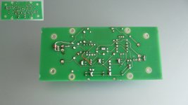
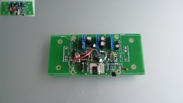
(below) NO SMD , just 6 resistor types / 6 semi types . Designed for
fat fingers.
Even designs with more than 16 semi's for the input stage are not
as popular. The parts count has to be where the builder can do it
in hours (not days). Attention span is key here.
I would consider a pre-assembled SMD input stage ,
but never a whole amp! No one would build it.
OS
Attachments
We're making a big effort to have both matched and unmatched LSK 170 and LSJ74 JFETS in the diyAudio store. It will take us a while to catch up, but you'll see some progress VERY soon, and more in another month. The matched ones tend to sell out in hours..
Your comments are right on target. I even invite suggestions for IPS, VAS and other devices that you and others feel would be good candidates in terms of both performance and availability.
I do share your concern regarding unobtainium devices, but note that the Linear Systems LSK389 dual, LSK170 and LSJ74 are available for making the dual complementary JFET input stages like those John Curl and others like. Of course, there is no dual monolithic p-channel available at this time, so some not-too-difficult matching of LSK74s is required.
Cheers,
Bob
Let's see..... If something is better, i will use it.
-RM
I am using SMD decoupling caps (1u, 50V, 1206 size) on the back of a board right at the pins of pamps, also SMD R's right at the gate pin of FETs. That sort of thing. In my view those are cases where SMD can actually improve performance. But I agree Richard, there's no general solution, you have to pick and chose the best technology for a specific case. SMD adds another choice to the palette.
jan
I am using SMD decoupling caps (1u, 50V, 1206 size) on the back of a board right at the pins of pamps, also SMD R's right at the gate pin of FETs. That sort of thing. In my view those are cases where SMD can actually improve performance.
I doubt SMD will make a difference in performance in audio electronics where you barely hit 1MHz and low gain. In the 80s, I designed discrete transimpedance amp and RF amp of 300MHz BW using TH transistors, resistors and capacitors. It's all on the layout, how much knowledge and care one puts in. SMD does not make up sloppy layout.
It's only above 300MHz into UHF that's when it get dicey with TH components. I doubt 1206 size has much advantage over a TH component. It's too big and has enough parasitic. If I go into SMD, it's going to be 0603 or 0402 for capacitors and 0603 for resistors. that's when SMD shines.
Luckily, the kind of circuit we work on in this forum are all low impedance circuits, nothing over 50K or so. Or else you need to be careful about surface contamination that cause leakage. SMD can trap dirt under the components and create a leakage path. I just designed a 100MV/A 3uS settling to 0.1% transimpedance circuit that the feed back resistor is 2512. I actually had to put a crater under the resistor so the resistor would not touch the surface of the pcb and trap dirt. If I have enough clearance, I would definitely use TH resistor.
In audio circuits like this, we don't push the high impedance and high frequency by any stretch, I really don't think component size has much to do with performance.
Last edited:
Well the SMD is on the bottom side and right up the pins, saving space on top, makes for a much or compact PCB, better all around. Once you go that way you'll see more an more advantages accrueing.
Jan
Jan
Attachments
Last edited:
I did, I designed all SMD for years. Mostly 6 layers boards, components on both sides and very high density. Attached is one of the high speed board I did with 16 channels 400MHz amps driving into ECL, FIFO and FPGA. You can see Blue and Gold color as top and bottom layers components. This one is not very dense because I had to avoid cross talk between those channels. You can zoom in to see all the details.Well the SMD is on the bottom side and right up the pins, saving space on top, makes for a much or compact PCB, better all around. Once you go that way you'll see more an more advantages accrueing.
Jan
Attachments
Last edited:
Good candidate for matched NPN/PNP couple is http://www.nxp.com/documents/data_sheet/BCM857BV_BS_DS.pdf, only noise figure a bit to high for a preamp, but for output amp is OK I think.
NPN/PNP matched couples are very useful for diamond in a CFA.
Maybe someone knows better suited NPN/PNP couple with lower noise?
Damir
Sorry it looks that this is PNP/PNP, the supplier where I normally bay says it's NPN/PNP
NPN/PNP matched couples are very useful for diamond in a CFA.
Maybe someone knows better suited NPN/PNP couple with lower noise?
Damir
Sorry it looks that this is PNP/PNP, the supplier where I normally bay says it's NPN/PNP
Last edited:
I did, I designed all SMD for years. Mostly 6 layers boards, components on both sides and very high density. Attached is one of the high speed board I did with 16 channels 400MHz amps driving into ECL, FIFO and FPGA. You can see Blue and Gold color as top and bottom layers components. This one is not very dense because I had to avoid cross talk between those channels. You can zoom in to see all the details.
Ahh yes, slightly more complex than my passive preamp -)
Hello Bob,
Hope you don't mind me asking, but will there be any measurements included this time around?
Hi Doug,
There were many measurements presented in the first edition, but you are probably referring to the evolution amplifiers in Chapter 3 where simulations were used to show how distortions were reduced as circuit improvements were made. When one is describing in tutorial fashion how individual circuit topology changes can make comparative improvements to performance, accurate simulations can be advantageous because the results are not influenced by unrelated effects due to real-world imperfections such as layout cross-talk, etc.
There will be numerous more measurements presented in the second edition. One useful exercise is to compare simulation results with measured results for a real amplifier. How close these come to each other is always a hot topic.
One other thing to point out that may have led to the wrong impression is that I did not show things like screen shots from an AP, since I do not own one. Thus, many of the measurements were presented as drawings of the data created in VISIO where the data came from my own THD analyzer, spectrum analyzer, or other equipment.
Cheers,
Bob
- Home
- Amplifiers
- Solid State
- Bob Cordell's Power amplifier book