Dadod,
I imagine we are talking about RNM doing the testing. The question I have is why wouldn't he use the power supply that you designed to go with the amplifier, or did you just send the board sans the power supply because of shipping costs? I would imagine that the bench power supply was a very well regulated supply, so what differences would you expect to see besides the long length of the connections?
I imagine we are talking about RNM doing the testing. The question I have is why wouldn't he use the power supply that you designed to go with the amplifier, or did you just send the board sans the power supply because of shipping costs? I would imagine that the bench power supply was a very well regulated supply, so what differences would you expect to see besides the long length of the connections?
No, this is not true. Early effect is modelled as a straight-line, which is not the case (see Fig 7.13 in APAD6)The Early voltage is properly modeled in spice
Definitely true. A huge number of SPICE BJT models show the Early parameter VAF as exactly 100 Volts, which is suspicious to say the least. I guess it's not of much interest to anyone not doing audio, so manufacturers don't bother with it.it's the lack of interest from the device manufacturers to provide the proper model parameters.
If you're saying that SPICE doesn't incorporate device operating limits then this is indeed true.Quasi-saturation is not - I find this the most annoying problem in the standard spice. It is also interesting to watch in spice BJTs blocked (with Ic=0) by Vbe=-25V.
If I am right that you speak about my amp then I have to add some explanation.
The amp was measured with the workshop power supply and long temporary connected wires. With the amp in proper chassis with proper power supply and proper wiring THD should be much lower.
Whats wrong with 20ppm ? That beats a lot of hi-end equipment.
What happens when you put it in an enclosure ? Short of a a separate regulated
supply in another enclosure , you will surely lose a few (ppm's).
It will pick up trafo EMF , RF from any 21'st century devices near it .....
Member 5thElement lost a little just measuring with his test leads in different
positions. A "dirty" world we live in (electrically) , especially after 1990 -
OS
Dadod,
I imagine we are talking about RNM doing the testing. The question I have is why wouldn't he use the power supply that you designed to go with the amplifier, or did you just send the board sans the power supply because of shipping costs? I would imagine that the bench power supply was a very well regulated supply, so what differences would you expect to see besides the long length of the connections?
Yes, I sent just the power amp boards. Nothing wrong with the bench power supply, but it was connected with long wires, with a power supply in the same chassis the wires could be shorter and twisted.
Whats wrong with 20ppm ? That beats a lot of hi-end equipment.
What happens when you put it in an enclosure ? Short of a a separate regulated
supply in another enclosure , you will surely lose a few (ppm's).
It will pick up trafo EMF , RF from any 21'st century devices near it .....
Member 5thElement lost a little just measuring with his test leads in different
positions. A "dirty" world we live in (electrically) , especially after 1990 -
OS
Nothing wrong with 20 ppm, just I hope that it could be lower as the simulation showed it ten times lower.
No, this is not true. Early effect is modelled as a straight-line, which is not the case (see Fig 7.13 in APAD6).
Yes, it is true. The Early effect is a linear dependence if Ic to Vce following Ic~(1+Vce/VA) where VA is the Early voltage. Therefore, in a small signal model, considering the Early effect leads to an output finite conductance of the BJT.
The nonlinear dependence Ic vs. Vce is the result of either (or both) of the non-uniform base doping, and approaching the base punch-through region. These effects are indeed not modeled in spice, however they don't fall under "Early effect". I would agree that these effects could be important e.g. in a VAS, because under large signal conditions, they modulate the VAS output conductance, and hence the VAS gain, resulting in nonlinearities.
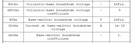
LTSpice does have models for high voltage leakage and breakover point. Would this be sufficient? I haven't used the parameters yet because I haven't worked out how to get the data, but maybe using them to model Vce curves is a step in the right direction?
Attachments
Yes, it is true. The Early effect is a linear dependence if Ic to Vce following Ic~(1+Vce/VA) where VA is the Early voltage. Therefore, in a small signal model, considering the Early effect leads to an output finite conductance of the BJT.
The nonlinear dependence Ic vs. Vce is the result of either (or both) of the non-uniform base doping, and approaching the base punch-through region. These effects are indeed not modeled in spice, however they don't fall under "Early effect". I would agree that these effects could be important e.g. in a VAS, because under large signal conditions, they modulate the VAS output conductance, and hence the VAS gain, resulting in nonlinearities.
I'm not saying it's correct, but everyone I know lumps all the Ic vs Vce effect together and calls it Early effect for convenience.
It's worth noting that the linear dependence as modelled in SPICE still gives rise to non-linearity in a VAS simulation. This is normally only significant at low frequences. (see APAD6 p175-p180)
I really wonder whether a lot of people here listen with their ears or with the spectrum analyzer and scope. This is audio equipments....appreciated by ears. Yes, you simulate distortion and all with LTSpice. But the ultimate is to listen to it.
The only reason I did the IPS/VAS with complementary IPS and push pull VAS si because the amp that got me into all these is YBA, they use this topology. They don't even have cascode for the LTP and use resistor load for the LTP. They are even more primitive. It sounds fantastic to me. In the showroom, it was jaw dropping.
There is so much more than just slew rate, distortion and clipping. Clipping is particularly easy to fix, use diode something like the good old schottky TTL way to prevent the transistor from going to FF region. It's easy to put one diode up and up diode down to replace schottky diode with a good old 1N4149!!! Clamp the collector and you'll never see the waveform sticking!!! Or better yet, like Mr. Self said, don't crank it!!!
I definitely going to do a Blameless IPS/VAS. It's easy as I have separate board for IPS/VAS, it's only going to be about $30 a run for 10pcb. But I just want to try the complementary topology for the sake of the YBA first.
Hey, the famous Nelson Pass has a blameless design in one of his Threshold, this is Nelson Pass!!! I saw he did not even optimize to Oliver's condition. But again, this is Nelson Pass and Threshold!!! I don't give a rat's A## how the schematic looks like, what the spectrum analyzer say. I listen to the sound. AND last check, this is audio amplifiers.....by definition, it's for the ears.
Last edited:
.I'm not saying it's correct, but everyone I know lumps all the Ic vs Vce effect together and calls it Early effect for convenience.
It's worth noting that the linear dependence as modelled in SPICE still gives rise to non-linearity in a VAS simulation. This is normally only significant at low frequences. (see APAD6 p175-p180)
Some do not; Prof Sansen discusses separately the linear Early effect distortion contribution, and then the high injection effects.
https://books.google.ca/books?id=FbzVBwAAQBAJ&pg=PA182&lpg=PA182&dq=%22linear+Early+effect%22&source=bl&ots=RW68ZdyZWl&sig=eBsgUP7b56SjsKIpLmEz03R-GRA&hl=en&sa=X&ei=B6uEVenwMczxoATJzLKQCw&ved=0CB0Q6AEwAA#v=onepage&q=%22linear%20Early%20effect%22&f=false
For a Golden Pinnae device, ALL listening is done with the eyes.Hey, the famous Nelson Pass has a blameless design in one of his Threshold, this is Nelson Pass!!! I saw he did not even optimize to Oliver's condition. But again, this is Nelson Pass and Threshold!!! I don't give a rat's A## how the schematic looks like, what the spectrum analyzer say. I listen to the sound.
Two visual features are paramount.
- $$$$ which must be as high as possible
- Famous names. I've conducted (sighted) Listening Tests that conclusively prove that G. Washington amps have better clarity & definition than GW Bush amps. The difference is jaw dropping.
Dadod, when THD gets to this level (or even well before) the layout, decoupling & earthing arrangements have equal or even greater importance than the circuit.Nothing wrong with 20 ppm, just I hope that it could be lower as the simulation showed it ten times lower.
Without being condescending, there are probably less than a literal handful of gurus on this august forum capable of the PCB and other design skills required to reliably get THD below 10ppm with the appropriate circuit.
Whether a 'proper' PSU will get better THD compared to Marshie's Regulated PSU depends on loadsa stuff. In most cases, an unregulated PSU will be worse but not always.
A New Distortion Mechanism in Class B Amplifiers iis just one of the factors but its not new. Baxandall was writing about this in the early 70's
Last edited:
Hi Alan0354,
-Chris
Gee, when I am designing or servicing, I listen and measure. The two agree or there is a problem. Each keeps the other honest.I really wonder whether a lot of people here listen with their ears or with the spectrum analyzer and scope. This is audio equipments....appreciated by ears.
-Chris
Hey, the famous Nelson Pass has a blameless design in one of his Threshold, this is Nelson Pass!!! I saw he did not even optimize to Oliver's condition. But again, this is Nelson Pass and Threshold!!! I don't give a rat's A## how the schematic looks like, what the spectrum analyzer say. I listen to the sound. AND last check, this is audio amplifiers.....by definition, it's for the ears.
But just one design , most Pass stuff is symmetrical. Or , symmetrical with IRFP
output stages (X250/350). I think Pass might consider the blameless like
Self does a symmetrical (or CFA).
I think the neatest arrangement is a "blend" of the standard LTP with a fully
symmetrical VAS (below). Member Vzaichenko measured <30ppm 20K with a
Valve as the first stage (in his version - http://www.diyaudio.com/forums/soli...erformance-yet-rather-simple-hybrid-more.html
. My builder used BJT's with more degeneration , but did
not have analysis capability. Simulation shows even the ability to have MORE
gain margin at 20K than a blameless. Sub PPM at 1-10Khz and better PSRR.
It's a 32 year old Sansui , repaired 3 of them .... main PS caps were shot ,
amps still worked on all 3 !!
Hey , it's not a CFA !! But , it's not a blameless either. There are many
good designs out there. Alan , when you start swapping out input stages ...
you will just see subtle differences in the presentation of your audio.
No one stage is so different that it is "bad" , unless it was improperly
designed in the first place.
OS
Attachments
Dadod, when THD gets to this level (or even well before) the layout, decoupling & earthing arrangements have equal or even greater importance than the circuit.
Without being condescending, there are probably less than a literal handful of gurus on this august forum capable of the PCB and other design skills required to reliably get THD below 10ppm with the appropriate circuit.
Whether a 'proper' PSU will get better THD compared to Marshie's Regulated PSU depends on loadsa stuff. In most cases, an unregulated PSU will be worse but not always.
A New Distortion Mechanism in Class B Amplifiers iis just one of the factors but its not new. Baxandall was writing about this in the early 70's
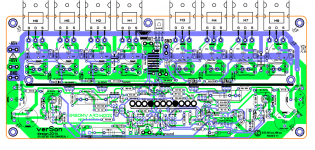
Kgrlee, yes I know all that but it's not easy to implement it to make perfect layout. I followed many discussion how to make good audio layout and this amp is my attempt to achieve all that, how good I am not sure.
Maybe you can comment on this layout, it is the one where I hope that distortion could go down when the boards are wired inside the chassis?
Attachments
Simulation is the most powerful tool in the box, but I hold that the only way to compare amplifier performance is with measurements of real amplifiers.
Hi DS,
I too have used Microcap sim software since day one of its release. However, I have also heavily invested in test equipment as well. I find today I am using the test equipment the most.
Dadod-
I listened to a modest system with your design; then with a big system. Today with the Quads. Always stable even with my ground-wire clip leads hanging all over the place. Noise on output (term with Electrostatic spkr) is 1.5mV with 400Hz-20KHz BW filter.
Might bring the -65 in on the right side of the pcb and the +65 in on the left side, as shown.
THx-RNMarsh
Last edited:
I hope to get a chance to measure the amp installed in a nice shielded chassis with good grounding etc. I was most pleased that the amplifier is very low in distortion but also it did not change much at all in distortion no matter what the Amp/Watts/Volts/Frequency/Z being used.
I'll test it more when i get it in a box.
The sound is very clean and detailed. The musical instrument or voice placement is very well delineated. Drums are tight and bass is deep and clean.... very realistic sound.
THx-RNMarsh
I'll test it more when i get it in a box.
The sound is very clean and detailed. The musical instrument or voice placement is very well delineated. Drums are tight and bass is deep and clean.... very realistic sound.
THx-RNMarsh
Last edited:
Dadod, I have to admit this PCB is very close to how I would do it.Kgrlee, yes I know all that but it's not easy to implement it to make perfect layout. I followed many discussion how to make good audio layout and this amp is my attempt to achieve all that, how good I am not sure.
Maybe you can comment on this layout, it is the one where I hope that distortion could go down when the boards are wired inside the chassis?
In particular, all the high current flows in what is almost a bunch of twisted wires.
For a Golden Pinnae device, ALL listening is done with the eyes.
Two visual features are paramount.
There are other important features ... eg hand carved from solid Unobtainium by virgins ... But if you get the two visual 'listening' features right, you can make the rest up.
- $$$$ which must be as high as possible
- Famous names. I've conducted (sighted) Listening Tests that conclusively prove that G. Washington amps have better clarity & definition than GW Bush amps. The difference is jaw dropping.
I disagree. I believe a lot of people do listen and find what they like, be that different people find different amp sounding better. I don't buy into people judge the amp by the price and the looks. High end brands are all very known, most of the names people never heard of it before. I went to the show room and listen to them blindly and just judge by ears. I for one never even heard of YBA, it looked cheap, it was just stunning when compare to my Acurus.
At the same time, I did listened to the well known names like Krell and Mach. I don't like them, those are the very one that the circuits are so complated, compensating for all distortion to the point it sounded dead to me.
Being a long time musician, I know how the real music sound, no recording remotely sounds like real life music, the last thing I want to judge is by a spectrum analyzer to to tell me which amp is good.
what is sound stage? Hell, most music records is a small studio, what stage? It's all about what sound the amp or speaker you like, not the spectrum analyzer.
I hope to get a chance to measure the amp installed in a nice shielded chassis with good grounding etc. I was most pleased that the amplifier is very low in distortion but also it did not change much at all in distortion no matter what the Amp/Watts/Volts/Frequency/Z being used.
THx-RNMarsh
That is a very interesting observation. It correlates well with simulated symmetrical/
CFA designs ,and even the leach. 20-30ppm almost right to clipping , any load
or frequency.
More so than some other designs.
What PS's do you have , Richard ? At least +/-50V ?
I will send
you a"slew" soon - I even have the extra "blameless" input stage (to test).
It's an orphan , as the other one is my subwoofer input stage.
I just have to populate it ....
Output stage is 3 pair Sanken MT-100 (150W) , I been using it to test input stages.
Once you have the output stage , input stages are easy to ship with 5$ USPS click and ship.
Just "plug them in" , afterwards.
OS
- Home
- Amplifiers
- Solid State
- Bob Cordell's Power amplifier book