Lets just see ....
I never directly compared the "blameless" to other designs in any manner other
than raw THD.
(Below 1) is PSSR. The blameless's CCS/filter versus the cancellation (+ccs's) of the "leach".
Blameless has better LF PSSR but the Leach is a bit better in the audio band.
A draw ?? Throw both behind a capacitance multiplier , both are >-110db (audio
band).
(below 2) is THD20 ... look at that , another "draw" !! EF3 as output stage ,
blameless without TMC. The lines have "blurred" , performance wise.
Offset might have to adjusted for the leach by adjusting it's two current sources ,
the only drawback.
(below 3) - clipping. Active clamp (bc550) on the darlington (blameless) -
Leach has it's native Hawksford cascode. Thing do look a bit "nastier" on the blameless. I'm sure 5ma saturation won't kill the bird , but 2.3ma is way better.
Some symmetric cascoded VAS's "self clamp" (baxandall) and have NO
saturation and a rounded waveform.
For the hell of it - I destroyed a tweeter with a blameless while the cascode
did not do this. No way around this. BTW - the VAS CCS also saturates
on the blameless. At least the saturation is symmetric.
Two methods for getting a very low distortion amp , both work VERY well.
But , one is not inferior to the other.
OS
Attachments
This is a new question:
What's the deal with the CFA? I read people kept talking about they are faster with better slew rate. I did simulations with the good old standard LTP IPS, they are plenty fast and good slew rate. I got large signal response into 400KHz. What is the point of over kill everything.
Particularly all the limitations are on the OPS, why do we want to kill ourselves over the IPS where it's never even in the bottle neck. Am I missing the moon here?
What is the point having an amp that can drive over 200KHz at large signal when you never hear anything over 20KHz.....How about 15KHz? OR 10KHz if you are old!!! Is this a case of way over blown that faster is always better?
What's the deal with the CFA? I read people kept talking about they are faster with better slew rate. I did simulations with the good old standard LTP IPS, they are plenty fast and good slew rate. I got large signal response into 400KHz. What is the point of over kill everything.
Particularly all the limitations are on the OPS, why do we want to kill ourselves over the IPS where it's never even in the bottle neck. Am I missing the moon here?
What is the point having an amp that can drive over 200KHz at large signal when you never hear anything over 20KHz.....How about 15KHz? OR 10KHz if you are old!!!
Is this a case of way over blown that faster is always better?Well, as I've argued elsewhere, frequency response, slewrate, noise etc are all more than good enough. If we seek the perfect amplifier, then distortion looks like the unsolved problem.
It does? In what way?
Look at the blameless clipping compared to the Baxandall hybrid -
(below 1). It does not saturate (at all).
And that design (below2 ) , is <10ppm 20K. OMG - it's a CFA !
It also sounds great , can be abused eternally - but it is a CFA.
It might have useless 250V/us slewrate and slightly poorer PSRR .
But we filter the rails a little , it's other attributes are stellar.
PS - I really don't believe >100V slew rate is a big factor , but
the impedance variations "transmitted" back to the FB node might
affect SQ.
OS
Attachments
From my understanding, CFA is all about the IPS, nothing to do with OPS. Just because you get higher frequency response on the IPS where the bottle neck is at the OPS?
We are talking about IPS/VAS here, not OPS. The output impedance has a lot to do with OPS. As I asked, what is the point of having the amp so fast where you can easily get 400KHz large signal with voltage feedback topology and plenty of slew rate. do we have to design RF amplifier for audio?
Where is the line drawn between real improvement vs psychosomatic?
Also, there are people that really love tube amp and Hiraga type amp that has much higher output impedance and interact with the speaker impedance.
Also who is to say that driving speaker with supper low impedance is better. You can look at it in another point of view that if the impedance of the speaker varies with frequency, if you drive the speaker with very low output impedance, your power delivered to the speaker varies with frequency!!! This is not exactly what I call low distortion and true reproduction by a long stretch.
What is the definition of good sounding? Or are we listening with the spectrum analyzer?
Last edited:
Also, there are people that really love tube amp and Hiraga type amp that has much higher output impedance and interact with the speaker impedance.
What is the definition of good sounding? Or are we listening with the spectrum analyzer?
Hiraga amps (8W and 30W) are CFB.
And "higher output impedance and interact with the speaker impedance" is a very good observation, but no one has interest in that, everybody is chasing zeros of thd...
Look at the blameless clipping compared to the Baxandall hybrid -
(below 1). It does not saturate (at all).
And that design (below2 ) , is <10ppm 20K. OMG - it's a CFA !
It also sounds great , can be abused eternally - but it is a CFA.
It might have useless 250V/us slewrate and slightly poorer PSRR .
But we filter the rails a little , it's other attributes are stellar.
PS - I really don't believe >100V slew rate is a big factor , but
the impedance variations "transmitted" back to the FB node might
affect SQ.
OS
You are trying to convert Douglas Self to anti-blameless-amp-constructor ??
I guess you have some better things to do Ha ha, that will be my next build. I don't really care one way or the other on the front end, I definitely going to do an OPS like that. I am very curious how it affect the sound.Hiraga amps (8W and 30W) are CFB.
And "higher output impedance and interact with the speaker impedance" is a very good observation, but no one has interest in that, everybody is chasing zeros of thd...
Absolutely right. It's only when you move from the Blameless configuration to one that is apparently more sophisticated, with double input stages/push-pull VAS, that you really appreciate how tolerant Blameless is in various ways. In Audio Power Amplifier Design (6th edition) I spent the whole of Chapter 8 looking at various double input stages/push-pull VAS and none of them were as good as a Blameless in any parameter, and there were usually unwelcome extra problems like drift of the input pair balance.
You gotta ask yourself, what are you hoping to gain with a double input stages/push-pull VAS configuration? I gather Alan0354 has already had some experience with the problems. Not wishing to discourage you, but it might be worthwhile to read Chapter 8 before putting too much time into this.
Hi Doug,
I agree, symmetry is beautiful to the eye on a schematic, but that does not mean that it really brings anything to the table. It is also fair to say that the full complementary differential input IPS provides more opportunities to get into trouble.
However, it is important to distinguish full complementary inputs and push-pull VAS. As explained in my book, I favor unipolar IPS with push-pull VAS. That is what I used in my MOSFET power amplifier in 1983, and its performance was superb. Of course, there are other good ways to do a unipolar IPS with a push-pull VAS, like in Tom Holman's legendary APT-1 power amplifier.
The very best input stages are JFET, and they generally must be unipolar (N-channel) unless one is to resort to unobtanium P-channel dual JFETs. Even with complementary JFETs, the full-complementary JFET input stages are more difficult to do right because of differences between the N-channel and P-channel JFETs.
Cheers,
Bob
You are trying to convert Douglas Self to anti-blameless-amp-constructor ??
No , but why are the "flagship" power amps of Accuphase , pass labs , H/K ,
and many- many others fully symmetrical designs ?
Could it be the overload factor ?
In my schematic collection , only some older mid-fi sony's are blameless , DIY
amps - blameless .... but not many OEM - proportionately.
OS
The very best input stages are JFET, and they generally must be unipolar (N-channel)
Ummmm... is this based on some solid technical reasoning, or is it just your preference?
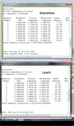
I never directly compared the "blameless" to other designs in any manner other
than raw THD.
(Below 1) is PSSR. The blameless's CCS/filter versus the cancellation (+ccs's) of the "leach".
Blameless has better LF PSSR but the Leach is a bit better in the audio band.
A draw ?? Throw both behind a capacitance multiplier , both are >-110db (audio
band).
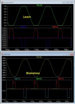
(below 2) is THD20 ... look at that , another "draw" !! EF3 as output stage ,
blameless without TMC. The lines have "blurred" , performance wise.
Offset might have to adjusted for the leach by adjusting it's two current sources ,
the only drawback.
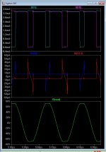
(below 3) - clipping. Active clamp (bc550) on the darlington (blameless) -
Leach has it's native Hawksford cascode. Thing do look a bit "nastier" on the blameless. I'm sure 5ma saturation won't kill the bird , but 2.3ma is way better.
OS
Simulation is the most powerful tool in the box, but I hold that the only way to compare amplifier performance is with measurements of real amplifiers. SPICE models are approximations, and in at least one case (BJT Early voltage) quite crude approximations.
Simulation is the most powerful tool in the box, but I hold that the only way to compare amplifier performance is with measurements of real amplifiers. SPICE models are approximations, and in at least one case (BJT Early voltage) quite crude approximations.
The Early voltage is properly modeled in spice, it's the lack of interest from the device manufacturers to provide the proper model parameters.
Quasi-saturation is not - I find this the most annoying problem in the standard spice. It is also interesting to watch in spice BJTs blocked (with Ic=0) by Vbe=-25V
.Ummmm... is this based on some solid technical reasoning, or is it just your preference?
Waly I think his reasoning is just right there in the part of the post you chose to cut off
Jan
I am quite happy to accept that CFAs can be much faster, but what's the point indeed? Conventional feedback amps can easily be designed with 10 times the slew rate required for full output at 20 kHz, and that seems to me a big enough safety-margin to prevent any slew-limiting ever. This is why I have never concerned myself with CFAs.This is a new question:
What's the deal with the CFA? I read people kept talking about they are faster with better slew rate. I did simulations with the good old standard LTP IPS, they are plenty fast and good slew rate. I got large signal response into 400KHz. What is the point of overkill everything.?
No, spot-on, IMHO.Particularly all the limitations are on the OPS, why do we want to kill ourselves over the IPS where it's never even in the bottle neck. Am I missing the moon here?
I think anything more than, say, a 10 times slewrate margin, is actually a bad thing. If HF instability occurs it is more likely to damage tweeters and output devices. There was one power amplifier (a Sony, I think??) which made a feature of very high slew-rate. It was famously unreliable and the despair of service engineers. I'm away from my archives at the moment- can anyone recall exactly which amplifier it was?What is the point having an amp that can drive over 200KHz at large signal when you never hear anything over 20KHz.....How about 15KHz? OR 10KHz if you are old!!!
Likewise, I think that a quite asymmetrical slewrate limit is good. If the amplifier bursts into oscillation, the resulting DC displacement will trip the DC-offset detector and open the output relay, saving the tweeters from immolation.
Look at the blameless clipping compared to the Baxandall hybrid -
(below 1). It does not saturate (at all).
And that design (below2 ) , is <10ppm 20K. OMG - it's a CFA !
To see much difference you have to be clipping some 20% of the time. That won't sound good with any amplifier.
My remedy is turn it down a bit.
Once you've activated your stapedius reflex (https://en.wikipedia.org/wiki/Acoustic_reflex) the perceived quality has gone to hell anyway. There is an optimal SPL for Maximum Musical Pleasure, probably around 80 SPL. YMMV
And few if any opportunities to get out of trouble.Hi Doug,
I agree, symmetry is beautiful to the eye on a schematic, but that does not mean that it really brings anything to the table. It is also fair to say that the full complementary differential input IPS provides more opportunities to get into trouble.
Personally, after my experiences in putting together Chapter 8 of APAD6, I don't find schematic symmetry beautiful to the eye. About as beautiful as the can of worms it can be in practice.
Hello Bob, hope you are well.
Certainly.However, it is important to distinguish full complementary inputs and push-pull VAS.
Simulation is the most powerful tool in the box, but I hold that the only way to compare amplifier performance is with measurements of real amplifiers. SPICE models are approximations, and in at least one case (BJT Early voltage) quite crude approximations.
Yes , I realize this. But I support the blameless Badger. Just had another builder
clip at 270W/4R and complain about the saturation.
That blameless just has a diode clamp addition. My newer wolverine has the option
for the diode or active clamp. The diode works best with tmc and the fast 2sa1381.
The transistor will produce that glitch when the saturation is clamped.
Either method still leaves the poor CCS to slightly saturate (trying to compensate
for the active sides misbehavior).
The simulator also PERFECTLY shows this saturation. (below) - just seen this
described and have seen scope shots of this same behavior.
BTW , with the cordell models .... those distortion figures are within ppm of
of the real amps. The blameless wolverine (with TMC) is 5ppm (real test-100w). It
also simulates the same.
You will not get accurate simulations if you use ideal sources , OEM models ,
or do not "cripple" the simulation with parasitic capacitance and inductance.
When my obsessed prototypers hit my design with square waves and
push it into overload - I have already seen the scope shots on the simulator.
What I posted is real close to the "truth".
The tests have only been with some real good PC based analyzers. I'm
about to send some amps to a forum member with a AP. He tested another
members CFA project at .002% THD20K/8R , similar to my CFA ....
I'm sure all (the symmetrical ips's) will be close.
The "blameless " rules. Short of Ed Stuart or Syn08's 40 device TIS's , no
other design can flirt with low single digit PPM at a 12 device count.
OS
Attachments
Firstly, modern computers easily output 96KHz sine waves. In a short time that can fry a Zobel, shift your quiescent to unsafe levels depending on design, or fry speakers either directly or due to excess DC offset caused by demodulation. If your amp/speakers can't safely accept 96KHz at full power (or even more with modern super-high samplerates), then you MUST have a good low-pass filter at the input, or have very good faith in the consumer! And yes, this is a realistic danger. Just one driver bug or crappy sequencer effect plugin could burn out a lot of stuff.
Secondly, BJT saturation isn't modeled perfectly but LTSpice does now have model parameters that include quasi-saturation and I think this gets us close enough for investigation in almost all cases - but most BJT models don't have it.
Did you know that many transistors are modeled with an excessive Hfe droop at normal Vce because the datasheet curves were taken partly in the quasi-saturation region? Yes, some transistors actually perform better than the simulation models.
Here are some models I made with quasi-saturation - they will only work in LTSpice:
.model BC337-40_kq NPN(IS=7.809E-14 Ibc=100f NF=0.9916 ISE=15f NE=1.4 Nk=0.55 BF=436.8 IKF=1.15 VAF=103.6 NR=0.991 ISC=6.66E-14 NC=1.2 BR=44.14 IKR=0.09 VAR=14 Rb=17.4 Kf=30f IRB=2.00E-04 RBM=8 RE=0.12 RC=0.05 Rco=3 XTB=0 EG=1.11 XTI=3 CJE=80p VJE=0.6657 MJE=0.3596 TF=620p XTF=1.5 VTF=2 ITF=0.5 PTF=88 CJC=1.306E-11 VJC=0.3647 MJC=0.3658 XCJC=0.455 TR=2.50E-08 CJS=0 VJS=0.75 MJS=0.333 FC=0.843 Vo=500 Gamma=4n Qco=8n Vceo=45 Icrating=800m mfg=OnSemi)
.model BC327-40_kq PNP(IS=2.077E-13 Ibc=230f NF=1.005 ISE=1.4f NE=1.3 NK=0.5 BF=475 IKF=.65 VAF=29 NR=1.002 ISC=2.963E-13 NC=1.25 BR=20.92 IKR=0.104 VAR=10 RB=17.4 Kf=240F IRB=1.00E-05 RBM=5.3 RE=0.14 RC=0.32 Rco=3.75 XTB=0 EG=1.11 XTI=3 CJE=115p VJE=0.9296 MJE=0.456 TF=500p XTF=3.25 VTF=2.5 ITF=0.79 PTF=80 CJC=2.675E-11 VJC=0.8956 MJC=0.4638 XCJC=0.459 TR=3.50E-08 CJS=0 VJS=0.75 MJS=0.333 FC=0.935 Vo=500 Gamma=10n Qco=8n Vceo=45 Icrating=800m mfg=OnSemi)
.MODEL 2SC4883A_kq npn (Bf=140 Ikf=100 Is=600f Vaf=100 Rb=1.7 Re=105m RC=0 Rco=6 Ibc=150f Vo=30 Gamma=250n Cje=1.2n Cjc=72p Tf=875p Vtf=1.2 Itf=1 Qco=8p Nk=1.2 Br=2 Var=23 Ikr=36 TR=85n Xtb=0.34 Xtf=1.36 Vceo=180 Icrating=2A mfg=Sanken)
.MODEL 2SA1859A_kq pnp (Bf=162 IKF=10 Is=500f Vaf=300 Rb=0 Re=0 Rc=90m Rco=3.25 Ibc=150f Vo=120 Gamma=22n Cje=1.5n Cjc=72p Tf=1.9n Vtf=1.9 Itf=1 Qco=8p Br=2 Ikr=10 Var=23 Tr=188.8n Xtb=0.138 Xtf=5 Vceo=180 Icrating=2A mfg=Sanken)
Notice there is a quasi-saturation parameter to affect Ft - Qco - which also allows us to model the sharp drop in Ft during quasi-saturation. Another anomaly that might only exist in current BJT models but not in actual devices when not in quasi-saturation.
PS - It is pretty useless to model the quasi-saturation of BC5xx transistors, so I gave up. At normal currents I could not find any significant quasi-saturation behavior.
Last edited:
To see much difference you have to be clipping some 20% of the time. That won't sound good with any amplifier.
My remedy is turn it down a bit.
Once you've activated your stapedius reflex (https://en.wikipedia.org/wiki/Acoustic_reflex) the perceived quality has gone to hell anyway. There is an optimal SPL for Maximum Musical Pleasure, probably around 80 SPL. YMMV
You don't know these builders ! They will hammer a new design into a 300W
fan cooled resistor load (at clipping) and complain if the resulting waveform
is not "textbook". VERY demanding around here
.OS
The tests have only been with some real good PC based analyzers. I'm
about to send some amps to a forum member with a AP. He tested another
members CFA project at .002% THD20K/8R , similar to my CFA ....
I'm sure all (the symmetrical ips's) will be close.
OS
If I am right that you speak about my amp then I have to add some explanation.
The amp was measured with the workshop power supply and long temporary connected wires. With the amp in proper chassis with proper power supply and proper wiring THD should be much lower.
- Home
- Amplifiers
- Solid State
- Bob Cordell's Power amplifier book