I suggest that you use ltspice to sim your design first before fabricating it. I am sure this is what Bob does now that ltspice is so common. It is always nice to compare the sim results with the actual circuit in operation and discuss the circuit operation with the thread followers.
Randy Sloan's schematic does not work, this is shown in Fig.7.9 in page 139 of Cordell's book. That's so obvious the current will fight, Took me one minute to notice that when I first decided to use dual CM for complementary LTP, I don't need no simulation to tell me. BUT the circuit shown in Fig. 7.10 works in my book. That's the circuit I used in my design and I believe it works. I don't need simulation to tell me. The two 47K R14 and R16 is the KEY to set the bias current in the VAS.
I believe using simulation when comes to the finer tweak like distortion etc. I think it is good practice to use common sense theory to look through the circuit to get deeper understanding of circuits rather relying everything on simulation. Never failed me yet in the last 30 years of designing RF, analog IC and all different complicated analog electronics.
I believe using simulation when comes to the finer tweak like distortion etc. I think it is good practice to use common sense theory to look through the circuit to get deeper understanding of circuits rather relying everything on simulation. Never failed me yet in the last 30 years of designing RF, analog IC and all different complicated analog electronics.
Last edited:
I attempted a similar topology design a while ago. The circuit certainly works in simulation. However in physical implementation you may have to pay special attention to the balance of the front end by selecting, screening, and matching the parts, as well as to the temperature balance and its compensation to the front end components that may have an impact to VAS operating current. As the standing current of the complementary VAS is sensitive to all those and a fluctuating VAS current is a bad news for OPS bias stability. Search the forum for meistersinger you may find that short thread. I was to give it up and has left the project alone for a good part of a year, then couldn't resist it and picked it up again, designed a layout using SMD dual transistors.
The amp is under construction, I hope with the matched components I will be able to have the VAS current fluctuation under control to a certain degree, then, if still not of satisfactory, I'll try the HK990 type of Vbe multiplier design that's immune to VAS current change.
Forum member Edmond Stuart proposed a solution to make the full complementary topology well behave. This following thread is a great discussion.
http://www.diyaudio.com/forums/solid-state/209658-has-anyone-seen-front-end-before.html
A common mode control loop is another working solution in stabilizing a complementary VAS standing current.
Attachments
Forum member Edmond Stuart proposed a solution to make the full complementary topology well behave. This following thread is a great discussion.
http://www.diyaudio.com/forums/solid-state/209658-has-anyone-seen-front-end-before.html
A common mode control loop is another working solution in stabilizing a complementary VAS standing current.
I looked at the schematic for a minute. I don't get what he is doing. But I don't see there is any current setting mechanism.
Seems like people are mixing up those complementary current mirrors of Sloan with the discussion here. I specifically talking about Fig. 7.10 in Cordell's book, not Sloan. This seems irrelevant to this discussion. Fig. 7.10 is a fix.
I looked at the schematic for a minute. I don't get what he is doing. But I don't see there is any current setting mechanism.
[....]

Looking for just one minute? Of course you don't get it.
What he was doing was to have a well defined and controlled VAS standing current, by having no current gain at the VAS. This would address the VAS current instability issue that you may likely be subject to, if you ever implement Fig. 7.10 without caution.
Fig. 7.10 has been well discussed in this forum, and there has been no disagreement that I know of about it being a fix to Sloan's undefined VAS current problem as you mentioned. However, Fig. 7.10 may still have VAS current drifting problem. If you have not tried it in simulation, better do it before sending out the Gerbers. I tried it by mismatching Hfe at one of the input transistor pair by 20% and the VAS current was quite sensitive.
Fig. 7.10 has been well discussed in this forum, and there has been no disagreement that I know of about it being a fix to Sloan's undefined VAS current problem as you mentioned. However, Fig. 7.10 may still have VAS current drifting problem. If you have not tried it in simulation, better do it before sending out the Gerbers. I tried it by mismatching Hfe at one of the input transistor pair by 20% and the VAS current was quite sensitive.
Hi Mr. Cordell
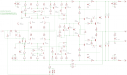
I have a question regarding to page 139 Fig.7.10. I designed the IPS/VAS just like Fig. 7.10 as shown in the attachment. I went through the theory and I am convinced this will work because like you said the 47K R14 stablized the voltage and set a stable current of the VAS.
BUT someone here claimed it does not work. He sited Sloan/Slone that it does not work!!! I don't see why. Can you confirm that Fig. 7.10 works? I am about to send out for pcb already, I have to put it on hold to confirm this.
Thanks
Which circuit doesn't work? If you mean the original circuit of Sloan, it doesn't work, that common knowledge. Otherwise if you mean Bob's fig 7.10, it might work, though I consider R14/R16 a stopgap. See also nattawa's comments.
What do you mean by sensitive? Say if I set for 10mA, how much would I expect to change? Seems like if too much imbalance in current, the 47K resistor can be reduced to lessen the effect. Say even down to 10K, it's still higher than if you resort to resistor load of the IPS.What he was doing was to have a well defined and controlled VAS standing current, by having no current gain at the VAS. This would address the VAS current instability issue that you may likely be subject to, if you ever implement Fig. 7.10 without caution.
Fig. 7.10 has been well discussed in this forum, and there has been no disagreement that I know of about it being a fix to Sloan's undefined VAS current problem as you mentioned. However, Fig. 7.10 may still have VAS current drifting problem. If you have not tried it in simulation, better do it before sending out the Gerbers. I tried it by mismatching Hfe at one of the input transistor pair by 20% and the VAS current was quite sensitive.
Last edited:
It does not have the resistor to set the current like in Fig. 7.10. I am not going to spend the time and change to a totally different circuit.
Looking for just one minute? Of course you don't get it.
Then don't spend your precious time by making s..... remarks about the SuperTIS.It does not have the resistor to set the current like in Fig. 7.10. I am not going to spend the time and change to a totally different circuit.
Good luck with fig. 7.10
Last edited:
Which part of my question SPECIFICALLY asking about Fig. 7.10 DON'T YOU UNDERSTAND?Then don't spending your precious time by making s..... remarks about the SuperTIS.
Good luck with fig. 7.10
Bob's fig 7.10, it might work, though I consider R14/R16 a stopgap. See also nattawa's comments.
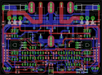
Well I hope it works; I'll find out soon enough, my boards will arrive any day now.
Attachments
What do you mean by sensitive? Say if I set for 10mA, how much would I expect to change? Seems like if too much imbalance in current, the 47K resistor can be reduced to lessen the effect. Say even down to 10K, it's still higher than if you resort to resistor load of the IPS.
I think I saw VAS current change of 2-3 mA, and that was by Hfe mismatching at one pair of transistor alone, before any Vbe mismatching and temperature stepping simulation that I didn't bother trying.
Yes, you can reduce the load resistor but that would further negates the point of using a current mirror.
Hi Mr. Cordell
I have a question regarding to page 139 Fig.7.10. I designed the IPS/VAS just like Fig. 7.10 as shown in the attachment. I went through the theory and I am convinced this will work because like you said the 47K R14 stablized the voltage and set a stable current of the VAS.
BUT someone here claimed it does not work. He sited Sloan/Slone that it does not work!!! I don't see why. Can you confirm that Fig. 7.10 works? I am about to send out for pcb already, I have to put it on hold to confirm this.
Thanks
Hi Alan,
The key to this circuit working is the 47k resistors across the collectors of each current mirror. The analogous circuit topology in Slone does not work because the standing current of the VAS is undefined. The 47k resistors act to define it. However, there is a tradeoff. The 47k resistors reduce the low-frequency open loop gain somewhat, although there is still plenty. The smaller the value of these resistors, the better the VAS standing current is defined in the face of resistor tolerances and transistor mismatches. But the smaller the value of the resistors, the more open loop gain at low frequencies you give up.
I think I discussed this in the book. I did a crude sensitivity analysis using multiple SPICE simulations with various deliberate mismatches. We generally would like to keep the VAS standing current to within +/-10% of its designed value in the face of reasonable mismatches.
Cheers,
Bob
Well I hope it works; I'll find out soon enough, my boards will arrive any day now.
You should be fine. The Vbe multiplier transistor in your design works in a constant Ic of about 1 mA, a fraction of VAS standing current. Most part of the VAS current, including fluctuation, gets bled off by Q22. i'd say your bias control is largely immune to the unstable VAS current, as long as VAS current stays greater than, say 2 mA, under all circumstances.
I'm using ThermalTrak transistors in the OPS in my amp, things are a bit more hazy there in handling the VAS current changes. I'll find that out.
the Sloan fail doesn't show in sim with the perfect matching of the Q models - have to unbalance by real world tolerances to see the VAS current wandering all over since the common mode V of the complementary diff output is only defined by secondary Q params
This is a very, very good point. I am a great believer in simulation, but it certainly does not substitute for good old circuit understanding. It also doesn't substitute for building the circuit.
Cheers,
Bob
Thank you very much Mr. Cordell. I designed for 10mA through the VAS, It does not matter whether it is 15mA or 5mA(+/-5mA). I think I have it covered. I used KSA1381 and KSC3503 with 50V max rail. I think I can take the variation.Hi Alan,
The key to this circuit working is the 47k resistors across the collectors of each current mirror. The analogous circuit topology in Slone does not work because the standing current of the VAS is undefined. The 47k resistors act to define it. However, there is a tradeoff. The 47k resistors reduce the low-frequency open loop gain somewhat, although there is still plenty. The smaller the value of these resistors, the better the VAS standing current is defined in the face of resistor tolerances and transistor mismatches. But the smaller the value of the resistors, the more open loop gain at low frequencies you give up.
I think I discussed this in the book. I did a crude sensitivity analysis using multiple SPICE simulations with various deliberate mismatches. We generally would like to keep the VAS standing current to within +/-10% of its designed value in the face of reasonable mismatches.
Cheers,
Bob
Just for curiosity, I use 300ohm for emitter degeneration for all 4 of the transistors of both differential pair. Does that help a lot on the balance? I run 2mA tail current for each LTP.
Thanks
Which circuit doesn't work? If you mean the original circuit of Sloan, it doesn't work, that common knowledge. Otherwise if you mean Bob's fig 7.10, it might work, though I consider R14/R16 a stopgap. See also nattawa's comments.
It does work, but as I stated above, and in the book, the designer must make a tradeoff between very high open loop gain at low frequencies (fairly useless anyway) and the value of the resistor across the collectors of the current mirror. It is a compromise, like most of our engineering decisions. In engineering, one man's simple stop-gap can be another man's elegant simple solution.
We should also keep in mind that the reason for, and benefit of, the current mirror load is not just higher gain, but also its enforcement of balance in the differential pair. The addition of the current mirror shunt resistor allows a simple circuit to use the full complementary current mirror approach without seriously impeding the current mirror's balancing function. Those many designs out there that forego the current mirror load for a simple resistive load can be subject to significant LTP imbalance.
Your circuit solution to this problem is quite brilliant, and very effective, but a bit more complex than some would choose. We pick our poison
.Cheers,
Bob
- Home
- Amplifiers
- Solid State
- Bob Cordell's Power amplifier book