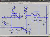
Thanks for this kean.kgrlee, here is my simulation. I did the same thing with an opposite-polarity frontend, and I don't see any strange harmonic cancellation. I do see that the EF reduces THD by ~34db, which is less than the OLG increase of 40db. Notice how few things changed between the schematics.
However, reversing the Hfe mismatch of Cordell's output models I'm able to reduce THD by almost half - most of the reduction in the 2nd harmonic. Just like the extra 5db reduction in THD you see in your plots. Without the enhancer, the effect isn't so large - no because it increases linearity but because the H2 cancellation goes out of tune.
Just three comments. I won't be able to do serious work on this for maybe a month.
- You need to be very careful looking at 'Open Loop' gain when you have high degrees of feedback (Loop Gain) I think my 14dB @ 40kHz may be too much let alone your 40dB
- The output stage hfe mismatch may be your 'missing distortion cancelling factor'. I'm quite aware of this. The final tweak for the original Blameless6 to get 1ppm @ 50W 20kHz (done for the tpc-vs-tmc-vs-pure-cherry) thread was to replace Self's MJE340/350 for Cordell's MJE243/253. In fact replacing just the MJE350 with MJE253 had substantial effect simply cos Bob's MJE350 model has much less hfe than his MJE340. Da CAGs like Bob would say why not just use an evil triple

But are you saying the enhancer's distortion was doing the cancelling? - I'm not sure you've adjusted the current mirror properly for optimum results with the 2 cases too.
Can you email me your .ASCs though I can't do anything with them for some time?
Bob, I'm generalizing but I think if you want 1ppm @ 50W 20kHz, you need to reduce every single distortion mechanism as you find them.I must admit that, philosophically, I don't like to depend on any matching of undesired effects; but maybe I am not giving the possible benefits enough credit.
Where 'distortion cancelling' is useful, is with a lesser target and you have a hair shirt mentality like mine which begrudges extra resistors let alone BJTs
My naive circuits, cos their distortions are predictable and hanging out, are easier to use one mechanism to cancel another. I don't think mismatched output hfe is a 'predictable' though
Bob, I'm being systematically shot down by kean but still fighting. But what's your opinion of evil Ccb in these simple designs? My position is still that its a 'dominant' mechanism
You'll note that as these examples don't take ANY feedback from the VAS output (ie they follow 'pure Cherry' philosophy) the THD is still mainly lower order even when 2nd/3rd are reduced.But what if that internal linearity is improved only by reducing the lowest-order harmonics, like in kgrlee's case?
Using evil types of compensation like Plain Miller, MIC, TPC & TMC will increase higher order harms and the residual will be A LOT spikier.
Last edited:
Hi Richard,
Anyway, I'm trying not to takes sides here, but to just point out why a single-number THD is limited in its usefulness. A THD result where the content of the first 7 or so harmonics is reported is probably more useful.
At the same time, I'll readily admit that a low number for 20kHz THD is a worthy goal among others, since it will allow less "wiggle room" for other nonlinearities to likely be problematic....... A SS amp with 0.001% THD20 is less likely to be having a lot of really bad high-order stuff because 0.001% can't mask as much bad stuff.
Cheers,
Bob
I fully agree. Just to keep things simple, I used THD in the discussion of nulling/cancelling.
Most to my thought is in agreement with: .001% THD20 will give very little 'wiggle' room for anything else.
Thx-RNMarsh
Last edited:
But are you saying the enhancer's distortion was doing the cancelling?- I'm not sure you've adjusted the current mirror properly for optimum results with the 2 cases too.
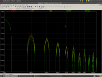
It is actually pretty easy to compare FFTs of the stages to see exactly where the cancellation occurs. Here we can see that the cancellation is a combined effect of the current mirror and R2. I had suspected the current mirror was responsible in part, but I didn't know just whether one was dominant or not.
It is easy to see that without making specific investigations, we'll be going around in circles with THD because we're tweaking cancellations of the remaining distortion rather than reducing it altogether.
Attachments
I don't care whether its TIS or VAS. Current can't be without voltage. Without voltage there's no current. It's different representations of quantities of energy. One usually picks what's easiest to work with.
That a VAS is called a VAS and may be seen as a voltage input is mostly because of how DC bias is performed. If you look at it from a voltage perspective, the VAS input is spread over Vbe and the emitter degen resistor. From this perspective, it's clear that the emitter resistor impacts gain.
But if you look at the very same scenario, but look at the base current instead as your starting point, then you can call it a TIS. Funnily the base current is a result of the voltage bias at the base in conjunction with the transistor's Beta and the emitter degen.
Pick your poison, it's all the same. That is my humble opinion.
I think John Curl's JC1 uses a MOSFET VAS configured as a folded cascode, IIRC.
Although I like MOSFETs in the output stage, I am not convinced that they bring any advantage to the VAS function.
I like amplifiers with JFETs in the IPS, BJTs in the VAS, and MOSFETs in the OPS.
Cheers,
Bob
In his Electronics World articles, Edward Cherry states that the gain-bandwidth product of small signal BJTs is greater than that of JFETs and that, therefore, BJTs are the prefered devices for the front end of an amplifier.
He further suggests that because the the gain-bandwidth product of MOSFETs is significantly greater than that of power BJTs, more feedback can, in theory, be applied around a MOSFET output stage.
Those interested in these articles should send me mail.
He further suggests that because the the gain-bandwidth product of MOSFETs is significantly greater than that of power BJTs, more feedback can, in theory, be applied around a MOSFET output stage.
Its a shame this theory isnt possible in reality and the reason outputstages using BJT outperform those of mosfets of similar design.
Current can't be without voltage. Without voltage there's no current.
You can in theory have current without a voltage if you consider an ideal current source driving a zero load impedance.
This is what the interface between the first and second stage of an amplifier of the Thompson topology aspires to be: an ideal current source driving the ideal short circuit.
If you look at it from a voltage perspective, the VAS input is spread over Vbe and the emitter degen resistor. From this perspective, it's clear that the emitter resistor impacts gain.
The TIS emitter resistor has no first order effect on forward path gain because the quantity of interest delivered by the first stage to the second stage is a current and not a voltage.
You can in theory have current without a voltage if you consider an ideal current source driving a zero load impedance.
Ideal current source is a voltage generator with infinite output impeadance, in this case no current without voltage. Probably in case of supraconductor, when the current was initiated there is no need for voltage any mor??
Its a shame this theory isnt possible in reality and the reason outputstages using BJT outperform those of mosfets of similar design.
when someone builds a audio amp with the IXYS DE series RF MOSFET?
Dadod, whats happened with the NGFB design of yours, some of us are waiting for PCB.
Which one, preamp or power amp?
I am implementing DC servo in the GainWire(first preamp not mk2) to see how it works in real world. After that I will do PCB for GainWire mk2(I am a bit busy with my TT amps for the Orion loudspeakers, ordered transformers arived).
An ideal current source assumes an infinite voltage source.(Sims advice zeners across ideal current sources to keep the initial voltage in limits. It can start out in GVs already otherwise) In practice there can be current and no voltage, or the other way around. Just grab an L or C. Both voltage and current describe together the electric energy both in motion and potential. My point still remains; both components are needed and are what give the desired results. It's just a matter of view on which component you see as 'leading' in your point of view.You can in theory have current without a voltage if you consider an ideal current source driving a zero load impedance.
But in practice the 2nd follower stage presents a load at which the IPS output will settle with a corresponding voltage. In practice, the NFB error signal can be viewed on this node as a voltage modulation. In the ideal world you can omit the voltage drive and assume current only. Here you pick current as the leading component to describe you theorem.'This is what the interface between the first and second stage of an amplifier of the Thompson topology aspires to be: an ideal current source driving the ideal short circuit.
Only naming of the second stage has been problematic; and the problem stems from what people view as the leading component, be it voltage or current. Well, they're both right. Distinct naming only makes sense if you want to make a difference at how the input is viewed.
That's exactly what I said: are you looking at it from a voltage drive perspective, or are you looking at just the current you're stuffing into the base of that transistor. You do the latter, and so you use TIS to make that particular distinction.The TIS emitter resistor has no first order effect on forward path gain because the quantity of interest delivered by the first stage to the second stage is a current and not a voltage.
Calling it a VAS is not wrong. In practice it's a voltage change at the input as much as it is a current change that propagates as a voltange change to the output. Using NFB, it's the error signal that drives a stage - you can look at this at either deltaV or deltaI whichever you prefer.
Last edited:
In practice it's a voltage change at the input as much as it is a current change that propagates as a voltange change to the output.
In general I find looking at a common emitter stage as current in voltage out a little bizzare. How about a common source stage with a FET? Now it makes even less sense.
Yeah exactly. You can even argue here that a delta Vgs Always comes with a delta Igs, charge/passthrough current. No matter how close to zero it is on DC. But generally manufacturers don't list this input current in their datasheet - they're voltage graphs instead. The current way of looking at fets is just not practical. With BJTs you have a choice. That's my take anyways.In general I find looking at a common emitter stage as current in voltage out a little bizzare. How about a common source stage with a FET? Now it makes even less sense.
Which one, preamp or power amp?
I am implementing DC servo in the GainWire(first preamp not mk2) to see how it works in real world. After that I will do PCB for GainWire mk2(I am a bit busy with my TT amps for the Orion loudspeakers, ordered transformers arived).

The power amp but one with the ODNF, the hawksford error correction one has too high THD, I had a look at the sims.
No worry Damir, Ill be patient, maybe Ill breadboard the input stage for now as Im also thinking of a new headphone amp.
That a VAS is called a VAS and may be seen as a voltage input is mostly because of how DC bias is performed. If you look at it from a voltage perspective, the VAS input is spread over Vbe and the emitter degen resistor. From this perspective, it's clear that the emitter resistor impacts gain.
Well, surprise surprise, it doesn't. Even if you feel an urge to consider the second stage as a VAS2, and therefore look at it as having a voltage gain, the emitter degeneration doesn't only reduce the VAS2 gain, but it is also increasing the VAS2 input impedance.
To calculate the end to end voltage gain, you now need to consider the input stage also as a VAS1. The VAS1 voltage gain is dependent by the load - more load impedance (VAS2 input impedance), more VAS1 gain.
Now pick a pencil and do some algebra. Either way you calculate (TCS * TIS or VAS1 * VAS2), the end to end voltage gain is gm*Rl*Beta where gm is the input stage transconductance (actually, 2*gm for a current mirror loaded input stage), Rl is the output stage input impedance and Beta is the VAS2 current gain (can be Beta1*Beta2 if a beta enhancer/emitter follower is used). As you see, the VAS2 emitter degeneration doesn't come into the equations.
VAS or TIS, there is no point in looking at the second gain stage in isolation. The fact that the VAS emitter degeneration lowers the VAS voltage gain is totally irrelevant in the context of the amplifier end to end gain.
An ideal current source assumes an infinite voltage source
Not at all! An ideal current source assumes a source that provides the set current irrespective of the load. Any output voltage is a byproduct of the current into a finite load.
An ideal voltage source assumes a source that provides a set voltage irrespective of the load. The current is a byproduct of the voltage across a finite load.
jan
but you can do the Thevenin/Norton interchange on them - giving the "infinite" Vsource in series with a "infinite" R such that V/R = I as a model of the ideal Isource
likewise "infinite" Isource in parallel with the "infinitesimal" R such that IR = V is a model of the ideal Vsource
likewise "infinite" Isource in parallel with the "infinitesimal" R such that IR = V is a model of the ideal Vsource
What is a Thompson topology?This is what the interface between the first and second stage of an amplifier of the Thompson topology ...
__________________
Will yus pedants arguing over VAS vs TIS, also factor in distortion.
Assuming a clean 'Voltage' output, one could consider a VAS one that requires 'undistorted' voltage input to produce this.
Similarly, an evil 'TIS' would require an 'undistorted' current input to produce clean output voltage.
That's what my #4042 & #4045 posts investigate. Of course in 'real life' a VAS/TIS is often very far from BOTH. My #4042 example is just closer to VAS.
Thus endeth the Technobable. [deleted: 3 pages of Pedantic Semantic Bable]
BTW, at the <10ppm THD levels of my examples, the VAS emitter resistor does have an effect on THD and also Loop Gain. You just have to look at the correct loop
I don't care whether its TIS or VAS. Current can't be without voltage. Without voltage there's no current. It's different representations of quantities of energy. One usually picks what's easiest to work with.
That a VAS is called a VAS and may be seen as a voltage input is mostly because of how DC bias is performed. If you look at it from a voltage perspective, the VAS input is spread over Vbe and the emitter degen resistor. From this perspective, it's clear that the emitter resistor impacts gain.
But if you look at the very same scenario, but look at the base current instead as your starting point, then you can call it a TIS. Funnily the base current is a result of the voltage bias at the base in conjunction with the transistor's Beta and the emitter degen.
Pick your poison, it's all the same. That is my humble opinion.
This is a fair way to look at it. Analogously, some prefer to view the amplifying characteristic of a transistor as current gain, while others prefer to view it as transconductance. Some argue over this. Both are "right". If one takes properly into account the various elements of the model and does the math right, the same correct answer comes out. One approach is more intuitive and convenient to some, while that is the case for the other approach for others.
Most terminology is imperfect in its description of whatever, and the choice of which imperfect description to use is not that important. However, it is helpful to be consistent, and that is why I have chosen to adopt the VAS terminology - the same as that used by Doug Self.
Cheers,
Bob
- Home
- Amplifiers
- Solid State
- Bob Cordell's Power amplifier book