Hi Bob,
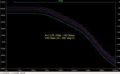
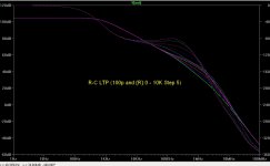
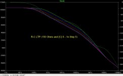
I did some simulations in an ideal circuit, did confusion, I say that capacitor in LTP has high attenuation, this is not true at the output of LTP the attenuation is 6dB/8°, The global effect can result in a high attenuation.
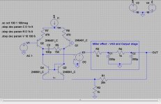
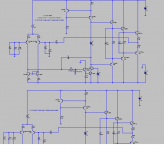
Here is my circuit and simulations:
I found best with a LTP real, the second order filter at the exit leave the circuit unstable.
I did some simulations in an ideal circuit, did confusion, I say that capacitor in LTP has high attenuation, this is not true at the output of LTP the attenuation is 6dB/8°, The global effect can result in a high attenuation.
Here is my circuit and simulations:
I found best with a LTP real, the second order filter at the exit leave the circuit unstable.
Attachments
Bob, I reckon you need to check the stability of the minor loop in figs. 3.13 & 3.14.
You've got three transistors in the minor loop; this is unlikely to be stable.
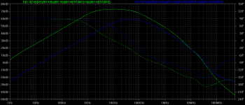
I have run a minor loop gain sim of your three transistor TIS (green trace) compared to the loop gain of a two transistor TIS (blue trace).
The three transistor TIS generates greater minor loop gain especially within the audio band, but is unstable, with a phase shift of 185 degrees at unity gain frequency, while the two transistor TIS has a phase shift of 153 degrees at unity gain frequency.
To stabilise the minor loop of the three transistor TIS you need at least 100pF shunt capacitance at the TIS output.
You've got three transistors in the minor loop; this is unlikely to be stable.
I have run a minor loop gain sim of your three transistor TIS (green trace) compared to the loop gain of a two transistor TIS (blue trace).
The three transistor TIS generates greater minor loop gain especially within the audio band, but is unstable, with a phase shift of 185 degrees at unity gain frequency, while the two transistor TIS has a phase shift of 153 degrees at unity gain frequency.
To stabilise the minor loop of the three transistor TIS you need at least 100pF shunt capacitance at the TIS output.
Attachments
Last edited:
Bob, I reckon you need to check the stability of the minor loop in figs. 3.13 & 3.14.
You've got three transistors in the minor loop; this is unlikely to be stable.
I have run a minor loop gain sim of your three transistor TIS (green trace) compared to the loop gain of a two transistor TIS (blue trace).
The three transistor TIS generates greater minor loop gain especially within the audio band, but is unstable, with a phase shift of 185 degrees at unity gain frequency, while the two transistor TIS has a phase shift of 153 degrees at unity gain frequency.
To stabilise the minor loop of the three transistor TIS you need at least 100pF shunt capacitance at the TIS output.
Hi Mike,
You make a good point. I'll check it out with some simulations. This is definitely an issue that I should address head-on in the second edition. In a number of cases I have been using a series R-C shunt on the VAS output node (even when not using MIC). Indeed, it has often been on the order of 100pF and maybe 100+ ohms.
I have also had some suspicion that issues like this have been partly involved in the instability of Triples that some have seen.
More recently, I've seen some interactions where I used a helper transistor on the IPS current mirror load. This was in cases where I used a VAS preceded by an EF and a Triple output stage.
One of the things, possibly related to all of this, that I have been looking more closely at is gain margin. I have seen numerous cases where there is above-band peaking in the closed-loop response. While this does not necessarily suggest dangerous instability, it can be a troubling wake-up call. 6dB of gain margin is often safe enough against oscillation, but it takes about 10dB of gain margin to have a monotonically decreasing closed loop response above the ULGF. Interestingly, in most cases where I have enforced a 10dB gain margin, phase margin was well over 60 degrees.
This underlines the need for people to measure the closed-loop response of modern amplifiers up to at least 10MHz.
In regard to gain margin, I have been looking for a term for its evaluation frequency that is analogous to ULGF for phase margin. That is, the frequency where 180 degrees of phase lag has accumulated, which is the point at which gain margin is evaluated. One acronym I have considered is "Inverting Loop Gain Frequency", ILGF, referring to the inversion of the loop gain when 180 degrees have accumulated. Another possibility I have considered is "Positive Loop Gain Frequency" PLGF. Do you know if anyone has coined a term for this frequency? What are your thoughts on this matter of convenient nomenclature?
Cheers,
Bob
UGF = unity gain frequency is a well accepted description of the frequency at which the open loop gain crosses below 0dB aka 1.00X (the final crossover, possibly among many).
In that spirit, why not PFPF = positive feedback phase frequency? The frequency at which the open loop phase crosses above 360 degrees (the first time). 180 degrees from the NFB amplifier, plus another 180 degrees from what old-timey Wireless World articles describe as "excess phase" (HF poles).
In that spirit, why not PFPF = positive feedback phase frequency? The frequency at which the open loop phase crosses above 360 degrees (the first time). 180 degrees from the NFB amplifier, plus another 180 degrees from what old-timey Wireless World articles describe as "excess phase" (HF poles).
UGF = unity gain frequency is a well accepted description of the frequency at which the open loop gain crosses below 0dB aka 1.00X (the final crossover, possibly among many).
In that spirit, why not PFPF = positive feedback phase frequency? The frequency at which the open loop phase crosses above 360 degrees (the first time). 180 degrees from the NFB amplifier, plus another 180 degrees from what old-timey Wireless World articles describe as "excess phase" (HF poles).
That only works until you start thinking about it. That name mixes cartesian and polar parlance. Polar coordinates don't have polarity, they have phase. Cartesian coordinates have polarity but not phase.
Bob, that resonance after the ULGF is trouble regardless of closed-loop stability. If you measure output impedance you'll find there is a peak there. The amplifier output node becomes an RF resonator. It is usually benign, but I try not to take the chance. You may have noticed that it is common to underdamp this resonance in order to lift phase at the ULGF so stability increases. Stability is thus dependent on the consistency of this resonance, which in all likelihood is the amp's output inductance resonating with the OPS parasitic capacitance. Both an amp's output inductance and its OPS capacitance can be (depending on compensation scheme) fully at the mercy of every parasitic element in the amplifier. Thus to attain reliability with this method one has to swamp out these parasitics and ends up losing whatever was gained, if anything was in the first place.
Making an amp stable and precise is hard work, and once one is finished they must immediately move on to the equally hard work of ensuring it behaves this way in all practical conditions without losing the performance gained in the previous step. A deep understanding of the inner mechanisms helps to ensure that one doesn't fall prey to constant regressions in design. Designing a reliable amplifier with great specs is an exercise in full design context.
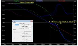
While I hesitate to say this is always the case, my experience has been that such 'above bandwidth peaking' is usually cos there is an inner loop that may have wonky stability. TMC and 'pure Cherry' are prone to this but even plain Miller can show this if the load on the VAS is wonky enough to affect its stability. The 'ULGF' of the inner loop is usually a lot higher than ULGF of the main loop.I have seen numerous cases where there is above-band peaking in the closed-loop response. While this does not necessarily suggest dangerous instability, it can be a troubling wake-up call.
I think you need to look at each internal loop if you see this. I'm also going to claim that if the Closed Loop response looks OK, all the inner loops will probably be OK.
")
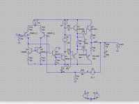
Here's a rather poor Pure Cherry example.
_____________________
[deleted 20 pg rant 'bout TLAs, FLAs and other evil obfuscating stuff ...In regard to gain margin, I have been looking for a term for its evaluation frequency that is analogous to ULGF for phase margin. That is, the frequency where 180 degrees of phase lag has accumulated, which is the point at which gain margin is evaluated. One acronym I have considered is "Inverting Loop Gain Frequency", ILGF, referring to the inversion of the loop gain when 180 degrees have accumulated. Another possibility I have considered is "Positive Loop Gain Frequency" PLGF. Do you know if anyone has coined a term for this frequency? What are your thoughts on this matter of convenient nomenclature?
]_____________
Another possible expansion to the 2nd Ed. might be more on RFI protection. Perhaps a simple diagram like Earthing Power Amps for good RFI as an example of good practice.
I was disappointed to find this Millenium that several very expensive and highly regarded Pro (?) Monitor powered speakers STILL announced to all & sundry that you'd received a SMS on your phone ... even with their 'professional' balanced inputs
Last edited:
In regard to gain margin, I have been looking for a term for its evaluation frequency that is analogous to ULGF for phase margin. That is, the frequency where 180 degrees of phase lag has accumulated, which is the point at which gain margin is evaluated. One acronym I have considered is "Inverting Loop Gain Frequency", ILGF, referring to the inversion of the loop gain when 180 degrees have accumulated. Another possibility I have considered is "Positive Loop Gain Frequency" PLGF. Do you know if anyone has coined a term for this frequency? What are your thoughts on this matter of convenient nomenclature?
Cheers,
Bob
Hi Bob,
If ULGF is well understood to mean unity loop gain frequency, then how about ZLPF (zero loop phase frequency)?
Regards,
Ian
Edit: I have seen articles referring to the gain & phase 'crossover' frequencies, but I dont think they are particularly descriptive terms. An example of such an article is http://www.library.cmu.edu/ctms/ctms/matlab42/freq/freq.htm
Last edited:
I've found the opposite to be true ! Are we allowed to disagree with AES peeps
Of course you can have any opinion you'd like!
Is this personal experience, is there a reasoning behind it?
jan
[..]
In regard to gain margin, I have been looking for a term for its evaluation frequency that is analogous to ULGF for phase margin. That is, the frequency where 180 degrees of phase lag has accumulated, which is the point at which gain margin is evaluated. One acronym I have considered is "Inverting Loop Gain Frequency", ILGF, referring to the inversion of the loop gain when 180 degrees have accumulated. Another possibility I have considered is "Positive Loop Gain Frequency" PLGF. Do you know if anyone has coined a term for this frequency? What are your thoughts on this matter of convenient nomenclature?
Cheers,
Bob
Hi Bob,
If ULGF is well understood to mean unity loop gain frequency, then how about ZLPF (zero loop phase frequency)?
Regards,
Ian
Hi Bob and Ian,
Any reference to the phase might lead to confusion, because several definitions of the phase are in common use. For example see Frank Wiedmann: The Designer's Guide Community Forum - Stb analysis
According to the one definition, the phase is zero at the frequency where the gain margin is measured and according to the other definition, the phase is 180 degrees. In order to avoid this ambiguity, what about Gain Margin Frequency, in short GMF?
Cheers,
E.
Last edited:
Hi Edmond,
That's a sensible suggestion.
It's a shame that 180 degrees has been previously defined, since the total phase around the entire loop at the GMF is 0. I suspect that 180 degrees implies the phase shift of the forward path, assuming that there is a subtractor at the front end of the loop which gives an additional -180.
Regards,
Ian
Edit: At university (far too many years ago), we were taught the Barkhausen Criterion regarding frequency of closed loop oscillation: http://en.wikipedia.org/wiki/Barkhausen_stability_criterion
This assumed nothing regarding the inclusion of a 'subtractor', so loop phase must be 0 or a multiple of 2pi radians.
Last edited:
In regard to gain margin, I have been looking for a term for its evaluation frequency that is analogous to ULGF for phase margin. That is, the frequency where 180 degrees of phase lag has accumulated, which is the point at which gain margin is evaluated. One acronym I have considered is "Inverting Loop Gain Frequency", ILGF, referring to the inversion of the loop gain when 180 degrees have accumulated. Another possibility I have considered is "Positive Loop Gain Frequency" PLGF. Do you know if anyone has coined a term for this frequency? What are your thoughts on this matter of convenient nomenclature?
Cheers,
Bob
No need to invent an acronym; for clarity simply stick to the frequency at which the phase is 180 degrees.
In this example certainly not. It is highly ambiguous.Plain english is always best !
More recently, I've seen some interactions where I used a helper transistor on the IPS current mirror load. This was in cases where I used a VAS preceded by an EF and a Triple output stage.
Cheers,
Bob
Would have been interesting to look into.
Was this by measurements or by simulation, if it was by measurement, was it a difference between simulation and measurements?
Could you be so kind as to post the schematic and the models you are using in the simulation?
Stein
Plain language is always best?
Cheers,
E.
BTW, although the ancient Romans were very clever in engineering, they didn't know the symbol "π". Instead, they consequently used the phrase "the ratio of a circle's circumference to its diameter". Rather clumsy, I would say.Plain english is always best !
Cheers,
E.
I just noticed peufeu posted up the link to these plots : DIY Test Equipment for Audio and Ham Radio Enthusiasts
What I'm curious to know is - some of these show interesting shaped noise floors. Are those noise floors the same as when unloaded or is the 50mA stimulus inducing some noise modulation in the regulators?
With a light or no load the series regulator pass elements will show higher Zout. I can redo the measuerments, but not for a few days.
- Home
- Amplifiers
- Solid State
- Bob Cordell's Power amplifier book