>I believe that JC is correct, because there loss of Slew Rate using output inductor.
Huh?
I can't believe that JC has said this.
Cheers,
E.
I said the loss Slew Rate, JC according to the account of an enthusiast, said that sound is better without the output inductor.
An output inductor does NOT affect the slew rate. It only affects the rise and fall time, being something else than slew rate.
Cheers,
E,
I always calculate the Slew Rate for rise time, the output inductor reduces mainly the rise time resulting in damped square wave.
Rafael L, I know that you mean well, but it is not 'slew rate' specifically that makes such a difference. In fact, I cannot tell you, precisely WHY significantly reducing the inductance of, or actually removing the output inductor actually makes a difference, BUT IT DOES!
What I was shown, actually by the engineers at Parasound, in Taiwan, that output conductors could be removed, in a PRACTICAL amplifier and virtually no harm would be done, BUT you would actually potentially improve the ultimate sound quality, and you could REDUCE the high frequency output impedance. Worth the effort.
What I was shown, actually by the engineers at Parasound, in Taiwan, that output conductors could be removed, in a PRACTICAL amplifier and virtually no harm would be done, BUT you would actually potentially improve the ultimate sound quality, and you could REDUCE the high frequency output impedance. Worth the effort.
Hi Bob
Unless I'm mistaken was John Curl who brought this claim. I believe that JC is correct, because there loss of Slew Rate using output inductor. You should know that Ex: one amplifier with 50V/us can only have 25V/us with output inductor. The loss of Slew Rate (resolution) is audible because it has compression of analog audio.
Another issue, many amplifiers are stable in "born" but not with 2m cable (practically a pure inductor 2uH) with a capacitive load R//C.
Hi Rafael,
The presence of an output inductor does not generally limit slew rate. My MOSFET power amplifier with error correction had an output inductor and it had a slew rate of 300V/us.
A claim that the output inductor can limit slew rate can easily be disproved by SPICE simulation. We are not talking about big inductors.
Cheers,
Bob
Why not? Audio amplifier is not a simple function generator, musical signal is much more complex than a sine wave.You don't need your amplifier to output ultrasound.
Some simulations:
No output inductor : Rise time 1,54 u/s - 40V/us
With output inductor(1u//1R): Rise time 1,98 u/s - 30V/us (node inductor - load)
With output inductor(1u//1R) + cable 2u: Rise time 2,36 u/s - 26V/us (node cable - load)
I should not be talking about anything new, loss of resolution in music (program material) is well known problem in recording studio (compression).
I don't need output inductors in any of my power amplifiers. I cannot say that SOME load, probably pretty exotic, might cause trouble, but not in normal operation, to the best of our experience with 1000's of Parasound amps out there, over the last 20+ years.
You could spend a few more details:
You use an RC filter on input?
You test the stability of their projects, with load//capacitive more meters of cable?
...BUT you would actually potentially improve the ultimate sound quality, and you could REDUCE the high frequency output impedance. Worth the effort.
A correctly designed (calculated) Thiel network at the output of an amplifier should have an inductor of no more than 2uH. This will not be audible, and will certainly not cause a significant increase in HF impedance.
Note that the insignificant rise in HF impedance of the inductor is more than compensated for by the typical rise in impedance at HF of the loudspeaker.
A typical speaker cable is 2-3 meters. At c. 1uH per meter, this is 2-3 uH and in a modern amp will swamp the output L (Assumption: fast bipolar or FET output stage). I use 0.5 to 1uH in my designs, with no ill effect on the sound. Worth the effort if you want stable amplifiers!
However, I do think its perfectly possible to build amplifiers that are very load tolerant without output L's. You need to make sure you have plenty of gain and phase margin, and under worst case load conditions, this means HF poles in the OP stage do not migrate down in frequency enough to full below the ULGF, hence with loop gains of >1 and P/S >180 degrees.
Use fast output devices and moderate loop gains to achieve this.
Hi Bonsai
If you have a good Slew Rate (larger than necessary) the loss Rise Time not is audible, my point was another an amplifier with less 50V/us, have an improved audible without an output inductor. This means that for those who will use an inductor output, should use a topology with high slew rate.
The method we use to calculate the slew rate is this:
High voltage amplifier - Bandwidth, high speed and slew rate
I can confirm this actually works very well and in fact the original thread was cos Fons (the clever gentleman I mention) was playing with this. You'll find substantial improvement in acoustic LF THD ...One thing I used to think was good was to set the negative output impedance of the amplifier to just cancel the voice coil resistance (but not down to DC, of course). This effectively made the speaker act in a constant velocity way and caused it to roll off at 6dB/octave over the band of interest (usually just low frequencies), so it needed electronic EQ up front. This is an over-simplified version of non-transdicer dependent speaker control, and is one way to use sensed speaker current.
.. and also with current drive. If you have a good way of measuring acoustic THD at LF, its worth trying simple versions of both these methods.In which case to me, it "suggests" that Current Drive "might" actually be beneficial ?
_________________
Yes. He was a Yank but studied under a couple of Aboriginal Elders so counts as an adopted OzzyOnly people who say Richard Small is an Ozzie He's actually American

I don't think his time at KEF was very fruitfull. Laurie Fincham kept Research very separate from Development and they never talked to each other. When I went to work for them, I was shocked at how little the speaker designers knew about Bass design ... especially when they had the world's chief guru on the subject in the next room for years.
Dr. Rhonda Wilson, a true blue Aboriginal Elder, will have the true goss. She worked with Dick Small during that period. But when I disappeared into the bush, she spread a vicious rumour that I'd been eaten by a crocodile
The output inductor is just like a low pass filter. If you do it right, it could reduce THD at high frequency (e.g. reduce THD @ 20KHz). You don't need your amplifier to output ultrasound.
Low-pass filtering the output of an amplifier to reduce THD does not make the amplifier sound better. THD-20 is just a metric of the amplifier's high-frequency linearity. Using THD-20 as a spec does not imply that ultrasonic harmonics are heard. Indeed, it is the in-band intermodulation products from high-frequency nonlinearity are what is usually responsible for impaired sound quality.
Cheers,
Bob
Do you think you could post a modified SPICE model of one of your good designs that does this? Practical device models please. (eg Bob's)However, I do think its perfectly possible to build amplifiers that are very load tolerant without output L's. You need to make sure you have plenty of gain and phase margin, and under worst case load conditions, this means HF poles in the OP stage do not migrate down in frequency enough to full below the ULGF, hence with loop gains of >1 and P/S >180 degrees.
Use fast output devices and moderate loop gains to achieve this.
This was a Holy Grail quest for me in da last Millenium.
 I can die happy once I learn how to do this. Sadly, the Son of God's designs don't cut it.
 Well, I always design WITH an output L, but here are some examples illustrating the point.
1st graphic is normal amp without L driving a (brutal) 2.2uF load - might be an Electrostatic panel for example. This amplifier is not stable and the phase margin insufficient.
In the 2nd graphic, the loop gain has been reduced - the diff amp degen resistors increased and Cdom doubled to set the ULGF to about 200 kHz. The output stage pole now sits higher than the ULGF even with the 2.2uF load. This amplifier is stable. BUT, the loop gain is reduced, so you pay a penalty for this approach in distortion performance. I did not optimize the ULGF - just stuck it very low at 200 kHz to illustrate the point - you could probably get away with something a little higher at 300 or 400 kHz.
The final graphic is the original high LG compensation design, but with a 2uH//10 Ohm load coupling network. Here the ULGF is 1 MHz (quite typcial for this type of design).
The kink in the LG you see at 77.912.6265322924 kHzD)is just the output coil resonating with the load capacitance.
Note, even with amplifiers that eschew an ouput inductor, you are still likely to see ringing as the speaker cable inductance resonates with the speaker capacitive load - there's no getting away from that one, but I guess as a speaker designer you already know that.
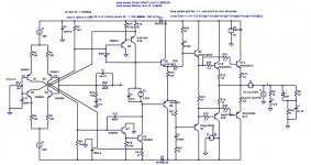
The last is the circuit of the amplifier - with the values of Cdom and Rdegen shown for low loop gain. There are probably more advanced compensation techniques that could be used in this design (TPC/TMC for example) to improve the distortion performance with the lower loop gain, but I have not addressed that here - this is purely illustrative. Note, the output coil with this low LG design is shown in situ in the circuit - for the plots, I shorted it out.
1st graphic is normal amp without L driving a (brutal) 2.2uF load - might be an Electrostatic panel for example. This amplifier is not stable and the phase margin insufficient.
In the 2nd graphic, the loop gain has been reduced - the diff amp degen resistors increased and Cdom doubled to set the ULGF to about 200 kHz. The output stage pole now sits higher than the ULGF even with the 2.2uF load. This amplifier is stable. BUT, the loop gain is reduced, so you pay a penalty for this approach in distortion performance. I did not optimize the ULGF - just stuck it very low at 200 kHz to illustrate the point - you could probably get away with something a little higher at 300 or 400 kHz.
The final graphic is the original high LG compensation design, but with a 2uH//10 Ohm load coupling network. Here the ULGF is 1 MHz (quite typcial for this type of design).
The kink in the LG you see at 77.912.6265322924 kHz
D)is just the output coil resonating with the load capacitance.Note, even with amplifiers that eschew an ouput inductor, you are still likely to see ringing as the speaker cable inductance resonates with the speaker capacitive load - there's no getting away from that one, but I guess as a speaker designer you already know that.
The last is the circuit of the amplifier - with the values of Cdom and Rdegen shown for low loop gain. There are probably more advanced compensation techniques that could be used in this design (TPC/TMC for example) to improve the distortion performance with the lower loop gain, but I have not addressed that here - this is purely illustrative. Note, the output coil with this low LG design is shown in situ in the circuit - for the plots, I shorted it out.
Attachments
Last edited:
Note, even with amplifiers that eschew an ouput inductor, you are still likely to see ringing as the speaker cable inductance resonates with the speaker capacitive load - there's no getting away from that one, but I guess as a speaker designer you already know that.
This is an important point. Often, we test our amps on the test bench with a very short test lead to the load and indeed we see differences with or without the output L.
But if you use, say, 10 ft speaker cable to the (dummy) load, in my experience most times you see absolutely no difference at the load, with or without the L.
You still might see differences at the amp output, and stability needs to be checked. But for the sound, which comes out of the speaker cable so to say, L or not is pretty irrelevant.
jan
- Home
- Amplifiers
- Solid State
- Bob Cordell's Power amplifier book