Hi,
there are not many examples of common collector output stage driven from a VAS. Le Monstre is one, 2SB716 is nothing else but 2SA872 in TO-92L package (I would not use it at more than 5 mA). Although pretty high distortion can be expected in the VAS, an intermediate stage would almost certainly ruin the performance. The design is not likely to be based on measurement.
there are not many examples of common collector output stage driven from a VAS. Le Monstre is one, 2SB716 is nothing else but 2SA872 in TO-92L package (I would not use it at more than 5 mA). Although pretty high distortion can be expected in the VAS, an intermediate stage would almost certainly ruin the performance. The design is not likely to be based on measurement.
Me too. What's with that?

Hi Nelson,
Darn, I should have thought of that! I would have been really honored to have had a review written by you.
Cheers,
Bob
Hello Bob,
I'd like to thank you for all the effort you put into your book. I've recently finished it and really enjoyed and appreciated the insights you provided, very well done.
I also like your comment above, except for the "at least some" aspect.
Years ago I had one of the high paid engineers tell me that designing without requirements is like throwing an arrow and painting a Bull Eye around it, I disagreed then (to some extent) and still do. I've always thought you design to please someone.
My home amps are to please my lovely wife (a linguist and music teacher “good ear”) who has always liked a good triode sound. Even with tubes she is discriminating, with my solid state versions I get the feeling she is just flattering me. Its really quite difficult, especially if you cant hear the same differences easily. Relating theory, designs, predictions, measurements to the satisfaction of the person you are designing for is in my opinion more than “at least some” worthy (sorry not meant to imply that a minimalist design is related to a tube sound).
Again, many thanks for your writings.
-Antonio
Hi Antonio,
Thanks for your very kind words about my book, and I'm really glad you liked it.
What makes this hobby great is that so many people get so many different things out of it. These amps all have a personality it seems, both in terms of sound and looks. Its great that people from the extreme subjective to the extreme objective can derive so much pleasure from audio. I've done numerous loudspeakers, and the feeling is the same. I enjoy the technical, I enjoy the sound, and I enjoy the woodworking. I've made great sounding speakers that are only so-so in the SAF department, but I've also been able to make some that are really good sounding and yet pleasing to Angela's eye.
I've also done a tube amp in recent years (the C70 on my site) and love it as well. I did numerous tube amps when I was a teenager (GOSH, I wish I still had those output transformers!), before I knew as much technically.
There are obviously many degrees of how much design and measurement various designers put into an amplifier, and different priorities as to where to put their energies. I think there are numerous designers (probably more than we think) who don't simulate in the design process and yet they produce exceptional sounding amplifiers. BTW, I did not simulate the C70 tube amp I did. However, I spent a lot of time with the frequency compensation, measuring its behavior, and checking its stability margins.
Cheers,
Bob
I would have been really honored to have had a review written by you.
Actually, I received an offer, but I would be uncomfortable saying either good or bad things about your work.
First you have to do that with the prototype. Then try to go "minimalist" with any of the building blocks, trying hard to make the right compromises in the performance vs. parts count arena. So you start at "simulate" again to make the final version (it's also nice to have the working prototype to confirm) , then you have to do something that only experience can define .. layout (below).
For DIY , one might not want to overwhelm the builder (121 parts is enough) , an OEM can make a 200mm X 400mm main board and trim the parasitic's after the fact (lucky them !) , 600 parts w . daughterboards is not uncommon.
And they are easier to refine , layout , thermally compensate. Most are lower power class A or bootstrapped LIN AB's ... hard to go wrong. For 120v p-p with acceptable or excellent linearity , you have to throw a few more parts in there.
PS - that's what the final "DBT" will be ( below). MUCH harder than a EF2 or Lateral OP.
OS
Hi OS,
It is certainly nice when a simpler design with fewer parts provides better performance. I have seen far too many designs where parts were thrown in as bandaids. We certainly don't want to go there. We also want those parts that we are using to be operating at their best. In the case of going from a double to a triple output stage, I think that the tradeoff is very positive in terms of adding the extra pair of small-signal devices as pre-drivers. Transistors are very imperfect devices - often some of the additions we make to a circuit are directly mitigating those imperfections (e.g., in the case of the triple, limited beta and drops in beta at high current). Similarly, a cascode mitigates Early effect.
Cheers,
Bob
Hi,
there are not many examples of common collector output stage driven from a VAS. Le Monstre is one, 2SB716 is nothing else but 2SA872 in TO-92L package (I would not use it at more than 5 mA). Although pretty high distortion can be expected in the VAS, an intermediate stage would almost certainly ruin the performance. The design is not likely to be based on measurement.
Hi WuYit,
By an intermediate stage ruining performance, do you mean the additions of a common collector stage to make the output stage a Darlington? If so, on what basis do you speculate the addition would "almost certainly ruin performance"?
Cheers,
Bob
Hi Bob,
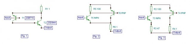
the output stage of Le Monstre is a compound consisting of a common emitter and a common collector amplifier according to Fig.1. An additional common collector stage in between would upset the favorable characteristics of the compound. Hiraga called it Darlingnot, the devices were carefully selected for sonic performance.
To me, the Complementary Feedback Pair (Sziklai Pair) is composed of two common emitter or common source amplifiers as in Fig.2. That in Fig.3 is not a CFP.
Attachments
What's the PSSR of Hiraga's Monster ?
I guess you already know the (sad) answer...

Hi Wahab
>I guess you already know the (sad) answer...
Not really but part of the response may rely in Jacco's comment :
>Oh, so that's where all the caps and batteries were for.
Details :
Amplificateur 8 W "Le Monstre". L'alimentation (J.Hiraga)
Page 13 :
With mains power supply, despite 180000 µF and q Pi filter, there is still some hum (happily said unaudible)
The next question is :
what's the output impedance of Hiraga's Monster ?
Amplificateur classe A 8 watts "Le Monstre" (J.Hiraga)
The chapter at the end of the initial article is measure and listening but the objective tests are confined to square waves. Everything else is usual subjective poetic prose.
forr,
I'd say it is more than low enough, 1 / ß, which is the output impedance of the voltage follower. Your previous question refers to the same thing. Do you think that it is the amplifier`s task to provide immunity against poor quality power supplies? I don`t think so. High PSRR and low output impedance are rather essential power supply properties.what's the output impedance of Hiraga's Monster ?
Bob,
in the CFP, two devices forming a tight loop, the master device decisively sets the properties of the compound, adding a stage would lead to loss of control (both AC and DC) and ordinary multi-stage feedback characteristics, also, more phase errors would aggravate the already fragile stability.
in the CFP, two devices forming a tight loop, the master device decisively sets the properties of the compound, adding a stage would lead to loss of control (both AC and DC) and ordinary multi-stage feedback characteristics, also, more phase errors would aggravate the already fragile stability.
forr,
I'd say it is more than low enough, 1 / ß, which is the output impedance of the voltage follower.
Numbers are somewhat more precise than low than enough, and measuring is better than supposition.
Have a look at the schematics underneath. Darlingnots are not followers for the amp output. Note that it if the two power supply nodes (two +12V nodes for the positive branch, two -12 V for the negative branch) are not tied together, any variation between them will be reflected in variation of current in the darlingnot.
Let's suppose they are tied together. The voltage across the 1 Ohm - 5W is equal to the voltage across the 1 kOhm resistor minus the SB716 (or 2SD756) Vbe and determines the current in the darlingnot feedback pair. This looks more like a Voltage Control Current Source than a follower.

PSRR describes the behaviour of a circuit towards its power supply. It does not describe the behaviour of both as an entity.Do you think that it is the amplifier`s task to provide immunity against poor quality power supplies? I don`t think so. High PSRR and low output impedance are rather essential power supply properties.
Don't you think that a huge power supply is an expensive remedy against the poor PSRR of an fanciful circuit ?
store $ range?
Me visited the shop at the original adress 2-3 times a year, long weekends in Paris or on the return trip from boozing in the S-E/S-W with the g/f, have nearly all l'Audiophile editions in hard copy, ~$11.5/pc in the '80s-'90s (aka read more, eat less).
My nose imprint is likely etched in the Western Electric tube glass window display they had in the store.
Last edited:
forr,
I'd say it is more than low enough, 1 / ß, which is the output impedance of the voltage follower. Your previous question refers to the same thing. Do you think that it is the amplifier`s task to provide immunity against poor quality power supplies? I don`t think so. High PSRR and low output impedance are rather essential power supply properties.
Hi WuYit,
Yes, it is important for any well-designed amplifier to have good PSRR. This does not let the power supply off the hook. It just means that for top quality you should have a clean supply AND an amplifier circuit that has inherently good PSRR. Sacrificing PSRR in the name of simplicity is probably the wrong way to go.
Cheers,
Bob
Bob,
in the CFP, two devices forming a tight loop, the master device decisively sets the properties of the compound, adding a stage would lead to loss of control (both AC and DC) and ordinary multi-stage feedback characteristics, also, more phase errors would aggravate the already fragile stability.
Hi WuYit,
It seems that you are talking in more generalities that appear to reflect your circuit instinct, which is not necessaily accurate. Have you simulated any amplifier circuits?
Saying things like "adding a stage would lead to loss of control (both AC and DC)...." comes across as just mumbo-jumbo.
Cheers,
Bob
Hi forr,
the properties of a stage are essentially determined by its topology, i. e. the input and output ports. The common collector amplifier, having fairly high input impedance and very low output impedance, excels as a voltage source, but would constitute an extremely poor quality current source. Both input and output signals being a voltage, the common collector amplifier is basically an impedance converter. On the other hand, the input voltage and the output current are loosely related; the Darlingnot ameliorates that relationship. ß is a product of the stages just like in the case of the Darlington pair and the CFP.
In Le Monstre, the bias current of the common collector amplifier is independent of its Vbe, the 1 Ohm resistor acting as a current source and Ibe of the common collector amplifier setting the current through the driver.
- Home
- Amplifiers
- Solid State
- Bob Cordell's Power amplifier book