Hello.
This amplifier is designed to not consume too much power
eventhough the output runs in True Class A.
Using 2 power transistors you will get 20 Watt across each.
The maximal output is around 8 Watt RMS
with very low distortion. (~0.003%)
Actually this amplifier is a spring off from my explorations into Pass ZEN amplifier.
But he uses no opamp to handle the feedback loop.
He takes the feedback right back to the MOSFET gate.
Original ZEN Amp from 1994: http://www.passdiy.com/pdf/zenamp.pdf
Using an opamp will be another cake.
Now we can begin talking real Hifi.
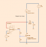
Here is the simplified diagram of my idea.
I post a detailed schematic later.
Regards Lineup")
This amplifier is designed to not consume too much power
eventhough the output runs in True Class A.
Using 2 power transistors you will get 20 Watt across each.
The maximal output is around 8 Watt RMS
with very low distortion. (~0.003%)
Actually this amplifier is a spring off from my explorations into Pass ZEN amplifier.
But he uses no opamp to handle the feedback loop.
He takes the feedback right back to the MOSFET gate.
Original ZEN Amp from 1994: http://www.passdiy.com/pdf/zenamp.pdf
Using an opamp will be another cake.
Now we can begin talking real Hifi.
Here is the simplified diagram of my idea.
I post a detailed schematic later.
Regards Lineup
Attachments
Hey, this looks interesting!
An idea: how about using a JLH output stage (with mosfets)?
Perhaps this could become the "ultimate" JLH ...
With "precision-enough" opamp, I think that it would have a very low DC-offset in case of symmetric supply as well.
(sorry to hijack)
An idea: how about using a JLH output stage (with mosfets)?
Perhaps this could become the "ultimate" JLH ...
With "precision-enough" opamp, I think that it would have a very low DC-offset in case of symmetric supply as well.
(sorry to hijack)
Last edited:
Interesting to hear about.The last year duild an proto of this amp.Work well.but my circuit have an small signal transistor in the second fet.
Somebody has the same idea as I have.
No, I havent Andrew.composite opamp & follower.
But you have not read Jung.
Thanks for posting.
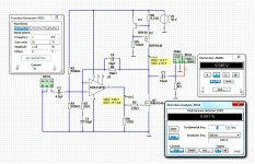
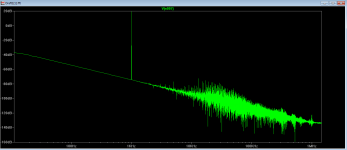
I have made a working design in SPICE.
It took me some hours
With a power supply of 30 Volt
it is possible to squeeze out more than 11 Watt RMS into 8 Ohm.
Class A.
As you can see from my picture here
Attachments
I don't know why, but something draws me to this design. The sheer simplicity without the MiFi of a Pass amplifier. According to the OPA134 sheet, the opamp can do +/-35mA. Is the 14.7 mA the max driving current?
And what would be changed in the design if instead of a mosfet a transistor was used and what would be the (dis)advantage of that?
And what would be changed in the design if instead of a mosfet a transistor was used and what would be the (dis)advantage of that?
Curious why you chose r6 to be 330 ohm. The datasheet for the opa134 shows 2k as optimum and 600 as minimum load for acceptable performance.
By the way, have you looked at Nelson's recent amp camp amp, a nice looking little circuit.
I wanted like 15-20 mA across the MOSFET gate.I don't know why, but something draws me to this design. The sheer simplicity without the MiFi of a Pass amplifier. According to the OPA134 sheet, the opamp can do +/-35mA. Is the 14.7 mA the max driving current?
And what would be changed in the design if instead of a mosfet a transistor was used and what would be the (dis)advantage of that?
I settled for 15 mA not to make the opamp work too hard.
I think it is possible to use 220 Ohm, but I also think 15 mA and 330 Ohm is enough to drive the big MOSFET alright.
In this case the output of MOSFET will probably swing 15mA, +/-5 mA. This is something OP134 can easily do. OPamp output will work totally in Class A
I have not followed what Nelson Pass has done recently. I want to look into that. There is always something to learn from him.
You have any link to his latest 'amp camp amp' ?
Looks nice.I am not so sure about the harmonics. Next to that, the BD140 model I had was not performing nicely so I used a different PNP, which seems to work better. (just randomly picked)
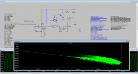
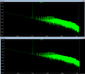
I did some FFT analys of my setup.
Shows 0.0001 % THD at 1 Watt.
Shows 0.0005 % THD at 8 Watt RMS output.
The FFT curve shows nothing bad.
I have no doubt this circuit will work i real life.
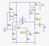
There is one think we should do - put a filter from the supply rail to the inverted input. Like it is now the opamp will pickup any hum from 30 Volt supply rail.
Now I have added a filter to the input, so to protect the input from the positive rail.There is one think we should do - put a filter from the supply rail to the inverted input. Like it is now the opamp will pickup any hum from 30 Volt supply rail.
Attachments
I have built circuits like these.
The only difference is that I used a resister for the current source.
They worked very good.
I was using about using stacked IRF510's and single IRF740's and IRF840's on close to 200v supply.
I made it in a bridged configuration and used it to drive a pizeo transducer very loud and cleanly.
It was before I had learned how to work with and design a solid state current source.
Great thread as I plan on visiting this topology again sometime soon!
Cheers !!!
jer
Last edited:
Just a wild thought.
Bias at 4A
Use 3 additional IRFP9240
Use 3 additional IRFP240
Change PSU to 40Vdc
Add a 30Vdc zener for OPA134 supply
Each Mosfet must dissipate around 20 Watt
Junction to case is 0.83 K/W
So 8 mosfets gives 0.104 K/W
Use a heatsink of 0.3K/W (big!)
Sum is 0.404K/W
160 Watt dissipation means a 65 degrees above ambient. Transistors get 25+65 is 90 Degrees Celsius and the heatsink gets 25+48 is 73 Degrees Celsius.
Class A is around 32 Watts on 4 Ohms!
Class A is around 16 Watts on 8 Ohms!
That's like building a F5.. Horrible, but doable.
Last edited:
- Status
- This old topic is closed. If you want to reopen this topic, contact a moderator using the "Report Post" button.
- Home
- Amplifiers
- Solid State
- 8 Watt Hifi with few parts