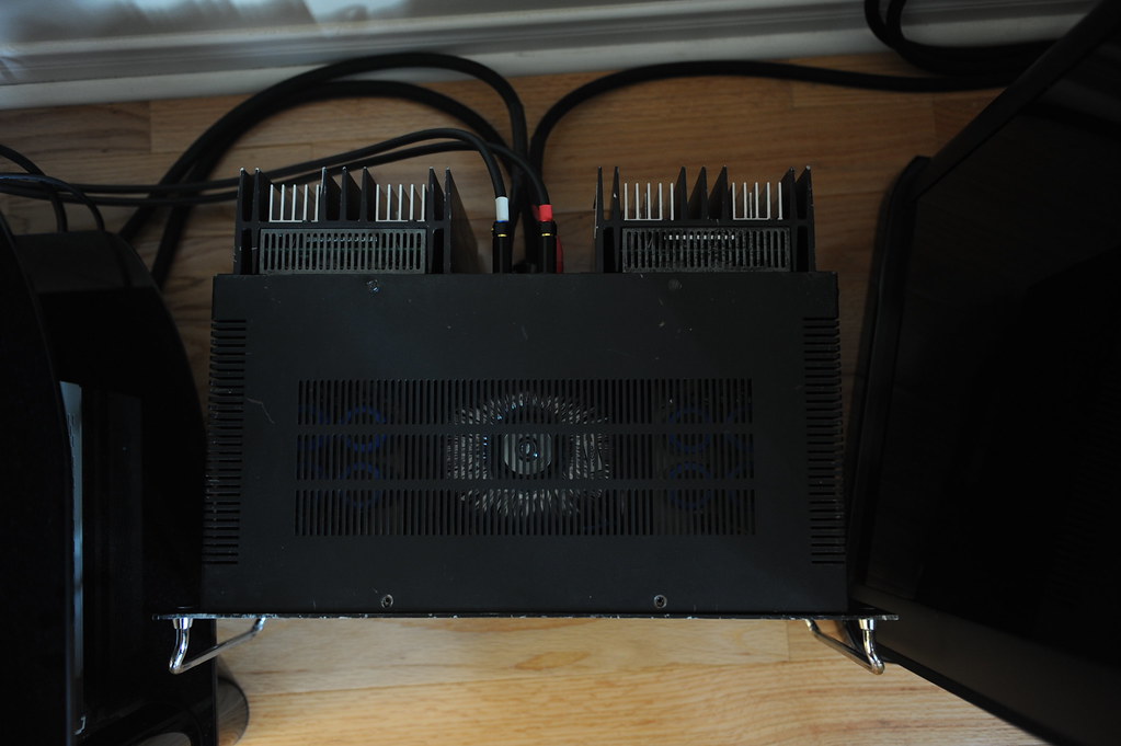
Bought a beaten-up Harman Kardon Citation 16 as a fixer-up unit and thought I’d fix whatever went wrong and it’d be my sleeper amp, only to end up with gutting this legend out completely. Now this amp has nothing but chassis and heat-sinks that are left over from the Citation Sixteen. It has two-channel Leach amp in it, with an output stage consists of 5-pair/channel ThermalTrak devices, NJL3281/1032 of On-Semi. By the way, could this be the first Leach Amp on TermalTrak output devices in this forum? Any ways here go the pics:
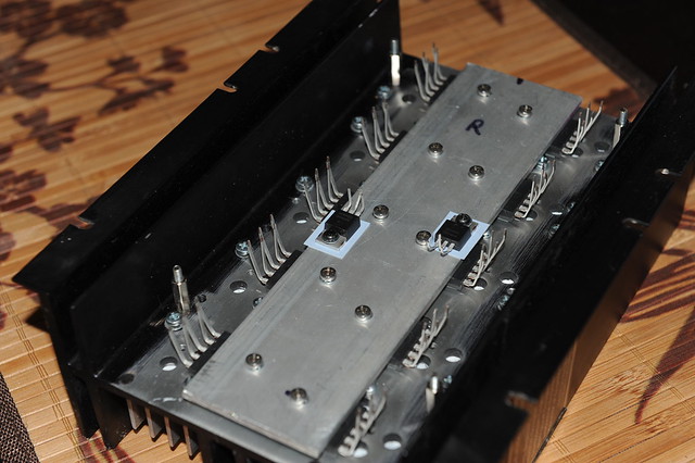
ALL-BUCKLED-UP...will it be a rough ride?
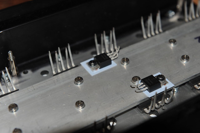
LITTLE DRIVERS…Can they handle the ark?
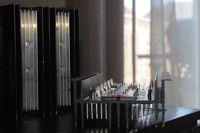
HEAT-AND-ITS-SINK
I piggy-back bolted some extra aluminum--scrap extrusion yet not particularly cheap from ebay-- to the center channel of the original Citation 16 heat-sink where the TO3s used to be to hopefully beef-up the heat-sinking capacity.
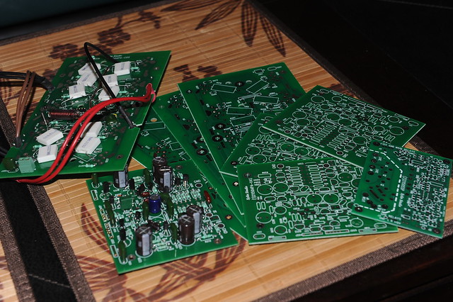
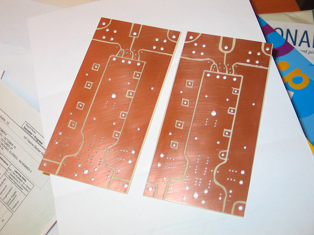
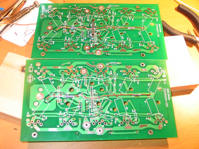
PCBS
Got these fabricated in China , cheap and in better-than-okay quality
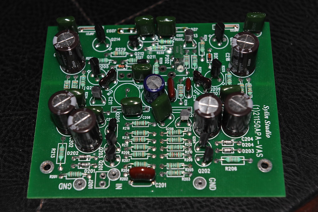
VAS
Voltage Amplification Stage assembled. I cut the GND copper foil to give the driver supply filter and the amplification stage supply filter separate ripple return paths after the PCB were made. The cuts show up on the component side as light marks mid way along the sides to the board edges
POWER-SUPPLY-BOARDS
These are hand-cut with a knife. The copper foils were later re-enforced with bus bars
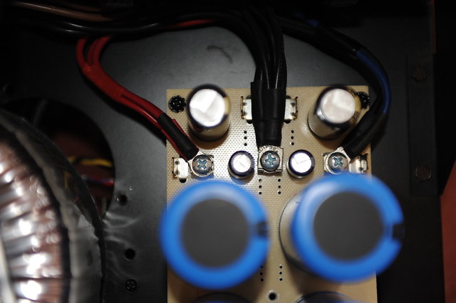
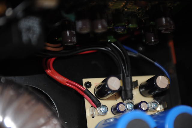
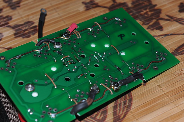
PWR-CONNECTORS
Ring lugs over Erni Power-Tap was my choice of power connection
POWER CONNECTIONS
Each Power-Tap connector receives 2 ring lugs. For the center GND there are 7 wires, 3 of them form a triple #14 gauge going to the speaker binding post, the other4 are driver supply filter return, amplification stage supply filter return, output zobel GND lead, and the signal GND reference. For the power connections there are 3 wires per each rail, one goes to the amplification and driver stage, and #14 doubled go to the output transistor common rail. Why double/triple the wires you ask? The butt end of my ring lugs is too large for a #14 stranded, plus they all say size matters
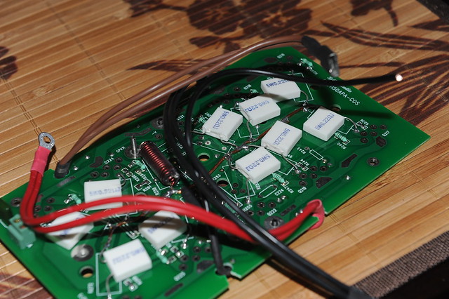
BUS-BAR-BOT-COS
Current output board gets bus bars on the supply rails. I also put in pem nuts for easy attachment of the ring lugs. They were first pressed on the PCB into the plated holes, then got soldered to the copper foil.
BUS-BAR-TOP-COS
The output node gets a bus bar too
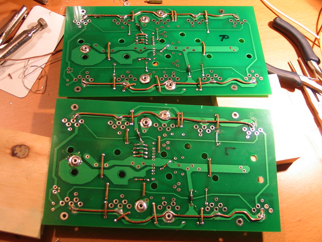
COS-BOT-WIRING
Ring lugs made doubled-up wiring easy
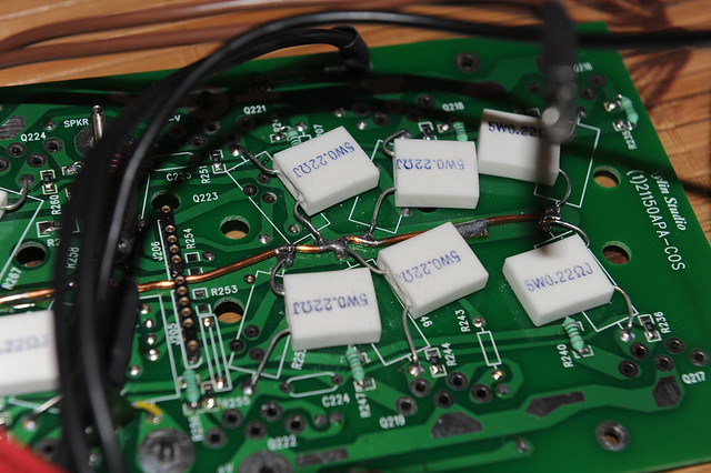
COS-DETAIL
Emitter resisters hooked up to the bus bar
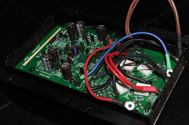
COS-WIRING
Current output stage ready to go onto the transistor/heat-sink assembly. Oh, noticed the 2-conductor terminal block at about the lower left corner in the picture? They are temperature sensor terminals reserved for on-die temperature measurement or warning/protection. Four out of the 10 ThermalTrak diodes are hooked up in series and wired up to this terminal block.
MODULAR-AMP
This is how the thing looks
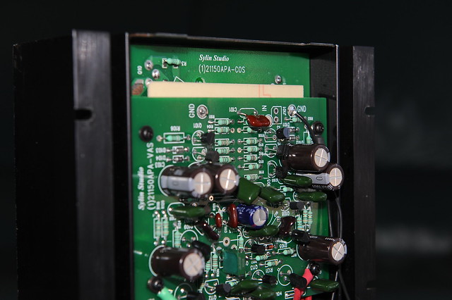
THE SHIELD
I sandwiched a third PCB of solid copper foil on GND in between the VAS and COS to cut down any possible capacitive couplings between the output stage and the input stage.

AMP-MODULE
Ready to go on the chassis and rock
AMP-OFF-CHASSIS
Powered up for the first time......with fingers crossed......
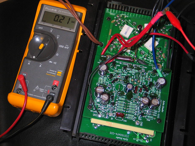
BIAS-ADJ
Started bias adjustment. I finally set the idle at 400mA to give the heat-sinks a nice warm touch. Stability has been good so far since the amp went into service a few months ago.
LEFT-CHNL-TOP
Left channel is on the chassis. The Neutrik RCA jacks look good, don’t they?
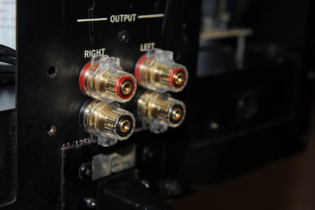
BINDING-POSTS
Are they too good?
R-CHNL-OFF-BINDPOSTS
Another view with right channel off chassis

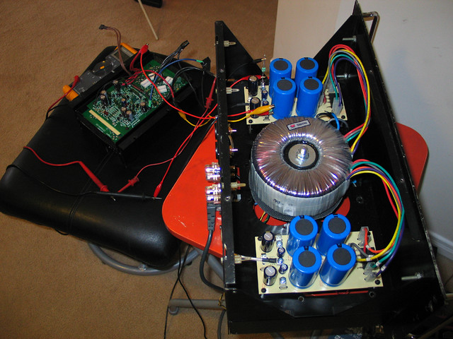
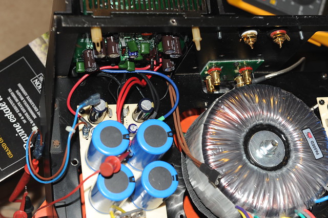
TOP-VIEW
All put together! This is the "living room" of the chassis. The two black blocks sitting next to the RCA jacks are the speaker relays. These are automotive relays with 80A contact capacity. The transformer looks nice in the chassis to me, despite the fact it was scavenged from a broken Behringer EP2500 power amp.
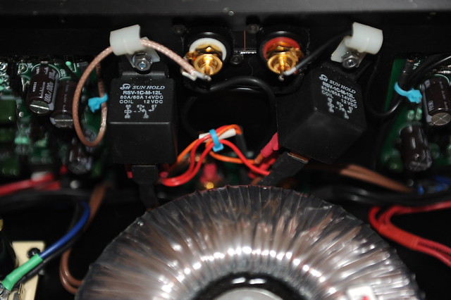
spk-rly-RCA-jack
A close up view
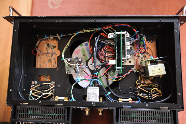
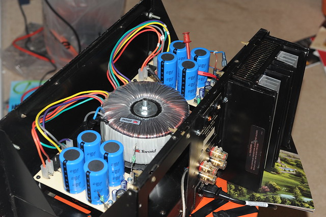
BOT-VIEW
Let's go to the basement and take a look at all the supporting components. There are a few assemblies there, working on a secondary power supply. The secondary power supply transformer was scavenged from a broken CD player
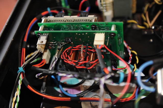
INRUSH-LIMITING
This PCB has three relays of 12A AC contact capacity on board for the mains. One to connect through thermisters, the other two in parallel bypass the in-rush control when the rails have become stabilized. It also controls two out-board relays to cut in and out speakers. (more on this later). The coiled up twisted black/red wires in the middle (a bit unsightly) are not connected at this time. They are reserved for working with protection mechanisms to shutting down the power. The PCB in green behind the inrush board is a piece of scrap and work as a supporting base for other PCB assemblies to attach to.

DISCHARGR
It discharges all 4 power rails quickly when power is turned off. (more on this later) The black chunk in the lower right is the power switch with lighting. It came with 12V incandescent bulb in it, but I don’t like the yellowish color so I replaced the bulb with 4 white LEDs in series.
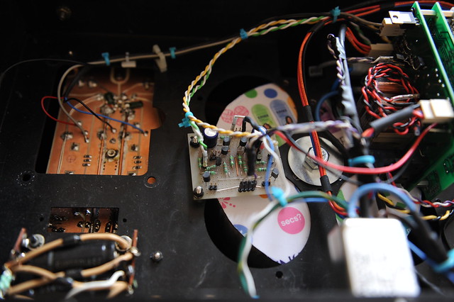
DC-DETECTION
It sends fault signals to the inrush PCB to have the speaker relay(s) cut out when DC is detected. It also lights up a warning LED indicating the channel in trouble.
IN-SVCE-TOP
Case closed.
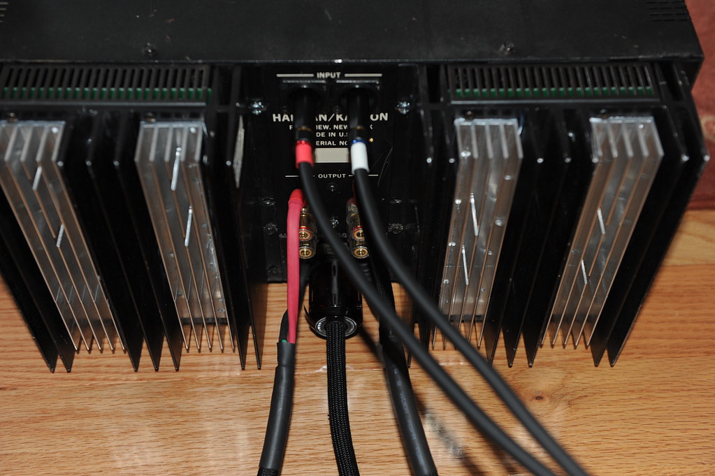
IN-SVCE-REAR
Ain’t her rear end smokin’ hot?
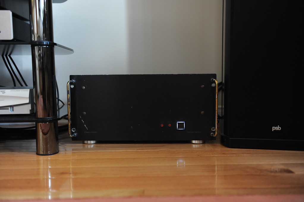
IN-SERVICE-Front
Hey, how do you like her in new shiny shoes? The original neon bulbs in the fixture have been replaced with LEDs that serve as DC warning. They seem to be glowing in the picture but they are in fact not. When they do they’d be much brighter than that.
My Paul-Sue-Barton’s are happy. So is the wifie. Beethoven has never sounded more Beethovenian.
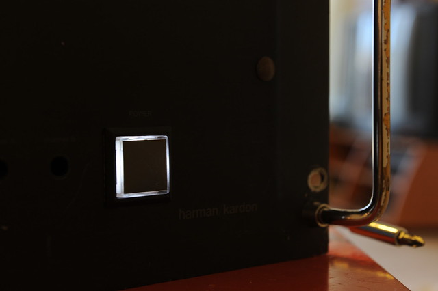
TOE-OPERATED
The power switch is a push-button momentary switch so that one could easily operate with a toe and save his/her back. Here is how to:
http://www.flickr.com/photos/21102007@N04/4833640424/in/set-72157624460926929/
I’d get my dog to learn to do that for me if I had one.
About the Inrush PCB: (schematic will follow)
The big toroidal power transformer of over 1KVA and 80,000uF smoothing capacitance have made inrush current limiting a must. This circuit is based on hard-wired logic/timer devices, it controls the mains power relays and speaker relays. It works on a 12VDC secondary supply. This was laid out on a two-sided PCB that requires some basic SMT soldering skills to assemble. The circuit works with a lighted push-button switch with momentary contacts as the power switch, each push starts a 5-second time window during which the switch itself is disabled and the switch lamp flashes. When start from standby the soft-start relay will engage for as long as the time window lasts (5s), the mains power is applied through three GE CL-40 NTC thermister in series (15 ohms in total at room temperature). This will limit the inrush current and charge up the main caps in a controlled manner. The main caps should be charged up well within the 5-s time window and the rail voltage flats out. A flat-out detection circuit will engage a power-good monitor and if a power-good is positive the circuit enters power-on mode, the main relays (two in parallel) will bypass the inrush limiter and connect the primary winding of the power transform directly to the mains supply, the lamp in the power switch stops flashing to glow at a normal brightness, the speaker relays will also engage at the same moment given that there is no DC detected at the amplifiers’ output. The soft-start relay then cuts out at the end of the 5-s time window. If no power rail flat-out is detected or no power-good is detected during the 5-s time window, the main relays and the speaker relays will not engage, and the circuit returns to standby mode at the end of the time window, the lamp in the power switch then stops flashing to glow a dim light. Pushing the power switch during power-on mode will simply disengage power relays and speaker relays, and a 5-s time window follows to allow the main caps to be discharged deeply enough prior to responding next button push.
About the Discharger: (schematic will follow)
It brings main caps down to under 5V a few seconds of power off. It was built on prototyping board. The discharger is engaged whenever all the mains power relays cut out, and disengaged when any of the mains relays actuates. There are 4 jumpers on the board that allow for disabling the discharging operation. I used 4 photo couplers to isolate the control side from the audio GND, as well as audio GNDs of left and right channels. Such isolation also allows a very simple and uniform circuit implementation on all power rails using power MOFETs of one single model.
DC detecting circuit: (schematic will follow)
It works in tandem with the soft-start PCB to cut out speakers when DC presents at the amplifier output, it lights up a warning LED of the channel in trouble too. Built on prototyping board.
To be implemented: (schematic suggestion welcome)
An on-die temperature measurement/warning/protection using the roughed-in temperature sensor.
ALL-BUCKLED-UP...will it be a rough ride?
LITTLE DRIVERS…Can they handle the ark?
HEAT-AND-ITS-SINK
I piggy-back bolted some extra aluminum--scrap extrusion yet not particularly cheap
from ebay-- to the center channel of the original Citation 16 heat-sink where the TO3s used to be to hopefully beef-up the heat-sinking capacity.
PCBS
Got these fabricated in China , cheap and in better-than-okay quality
VAS
Voltage Amplification Stage assembled. I cut the GND copper foil to give the driver supply filter and the amplification stage supply filter separate ripple return paths after the PCB were made. The cuts show up on the component side as light marks mid way along the sides to the board edges
POWER-SUPPLY-BOARDS
These are hand-cut with a knife. The copper foils were later re-enforced with bus bars
PWR-CONNECTORS
Ring lugs over Erni Power-Tap was my choice of power connection
POWER CONNECTIONS
Each Power-Tap connector receives 2 ring lugs. For the center GND there are 7 wires, 3 of them form a triple #14 gauge going to the speaker binding post, the other4 are driver supply filter return, amplification stage supply filter return, output zobel GND lead, and the signal GND reference. For the power connections there are 3 wires per each rail, one goes to the amplification and driver stage, and #14 doubled go to the output transistor common rail. Why double/triple the wires you ask? The butt end of my ring lugs is too large for a #14 stranded, plus they all say size matters
BUS-BAR-BOT-COS
Current output board gets bus bars on the supply rails. I also put in pem nuts for easy attachment of the ring lugs. They were first pressed on the PCB into the plated holes, then got soldered to the copper foil.
BUS-BAR-TOP-COS
The output node gets a bus bar too
COS-BOT-WIRING
Ring lugs made doubled-up wiring easy
COS-DETAIL
Emitter resisters hooked up to the bus bar
COS-WIRING
Current output stage ready to go onto the transistor/heat-sink assembly. Oh, noticed the 2-conductor terminal block at about the lower left corner in the picture? They are temperature sensor terminals reserved for on-die temperature measurement or warning/protection. Four out of the 10 ThermalTrak diodes are hooked up in series and wired up to this terminal block.
MODULAR-AMP
This is how the thing looks
THE SHIELD
I sandwiched a third PCB of solid copper foil on GND in between the VAS and COS to cut down any possible capacitive couplings between the output stage and the input stage.
AMP-MODULE
Ready to go on the chassis and rock
AMP-OFF-CHASSIS
Powered up for the first time......with fingers crossed......
BIAS-ADJ
Started bias adjustment. I finally set the idle at 400mA to give the heat-sinks a nice warm touch. Stability has been good so far since the amp went into service a few months ago.
LEFT-CHNL-TOP
Left channel is on the chassis. The Neutrik RCA jacks look good, don’t they?
BINDING-POSTS
Are they too good?
R-CHNL-OFF-BINDPOSTS
Another view with right channel off chassis
TOP-VIEW
All put together! This is the "living room" of the chassis. The two black blocks sitting next to the RCA jacks are the speaker relays. These are automotive relays with 80A contact capacity. The transformer looks nice in the chassis to me, despite the fact it was scavenged from a broken Behringer EP2500 power amp.
spk-rly-RCA-jack
A close up view
BOT-VIEW
Let's go to the basement and take a look at all the supporting components. There are a few assemblies there, working on a secondary power supply. The secondary power supply transformer was scavenged from a broken CD player
INRUSH-LIMITING
This PCB has three relays of 12A AC contact capacity on board for the mains. One to connect through thermisters, the other two in parallel bypass the in-rush control when the rails have become stabilized. It also controls two out-board relays to cut in and out speakers. (more on this later). The coiled up twisted black/red wires in the middle (a bit unsightly) are not connected at this time. They are reserved for working with protection mechanisms to shutting down the power. The PCB in green behind the inrush board is a piece of scrap and work as a supporting base for other PCB assemblies to attach to.
DISCHARGR
It discharges all 4 power rails quickly when power is turned off. (more on this later) The black chunk in the lower right is the power switch with lighting. It came with 12V incandescent bulb in it, but I don’t like the yellowish color so I replaced the bulb with 4 white LEDs in series.
DC-DETECTION
It sends fault signals to the inrush PCB to have the speaker relay(s) cut out when DC is detected. It also lights up a warning LED indicating the channel in trouble.
IN-SVCE-TOP
Case closed.
IN-SVCE-REAR
Ain’t her rear end smokin’ hot?
IN-SERVICE-Front
Hey, how do you like her in new shiny shoes? The original neon bulbs in the fixture have been replaced with LEDs that serve as DC warning. They seem to be glowing in the picture but they are in fact not. When they do they’d be much brighter than that.
My Paul-Sue-Barton’s are happy. So is the wifie. Beethoven has never sounded more Beethovenian.
TOE-OPERATED
The power switch is a push-button momentary switch so that one could easily operate with a toe and save his/her back. Here is how to:
http://www.flickr.com/photos/21102007@N04/4833640424/in/set-72157624460926929/
I’d get my dog to learn to do that for me if I had one.
About the Inrush PCB: (schematic will follow)
The big toroidal power transformer of over 1KVA and 80,000uF smoothing capacitance have made inrush current limiting a must. This circuit is based on hard-wired logic/timer devices, it controls the mains power relays and speaker relays. It works on a 12VDC secondary supply. This was laid out on a two-sided PCB that requires some basic SMT soldering skills to assemble. The circuit works with a lighted push-button switch with momentary contacts as the power switch, each push starts a 5-second time window during which the switch itself is disabled and the switch lamp flashes. When start from standby the soft-start relay will engage for as long as the time window lasts (5s), the mains power is applied through three GE CL-40 NTC thermister in series (15 ohms in total at room temperature). This will limit the inrush current and charge up the main caps in a controlled manner. The main caps should be charged up well within the 5-s time window and the rail voltage flats out. A flat-out detection circuit will engage a power-good monitor and if a power-good is positive the circuit enters power-on mode, the main relays (two in parallel) will bypass the inrush limiter and connect the primary winding of the power transform directly to the mains supply, the lamp in the power switch stops flashing to glow at a normal brightness, the speaker relays will also engage at the same moment given that there is no DC detected at the amplifiers’ output. The soft-start relay then cuts out at the end of the 5-s time window. If no power rail flat-out is detected or no power-good is detected during the 5-s time window, the main relays and the speaker relays will not engage, and the circuit returns to standby mode at the end of the time window, the lamp in the power switch then stops flashing to glow a dim light. Pushing the power switch during power-on mode will simply disengage power relays and speaker relays, and a 5-s time window follows to allow the main caps to be discharged deeply enough prior to responding next button push.
About the Discharger: (schematic will follow)
It brings main caps down to under 5V a few seconds of power off. It was built on prototyping board. The discharger is engaged whenever all the mains power relays cut out, and disengaged when any of the mains relays actuates. There are 4 jumpers on the board that allow for disabling the discharging operation. I used 4 photo couplers to isolate the control side from the audio GND, as well as audio GNDs of left and right channels. Such isolation also allows a very simple and uniform circuit implementation on all power rails using power MOFETs of one single model.
DC detecting circuit: (schematic will follow)
It works in tandem with the soft-start PCB to cut out speakers when DC presents at the amplifier output, it lights up a warning LED of the channel in trouble too. Built on prototyping board.
To be implemented: (schematic suggestion welcome)
An on-die temperature measurement/warning/protection using the roughed-in temperature sensor.
Last edited:
well ... eventhough that looks like a hell of a lot of work to do ...also costly from the built and quality of parts your constructions is kinda messy...i am pretty sure that it could be done better
probably the comment has nothing to do with sound and still your amp might play like hell but still investment like that could be also done for the looks
other than that seriously well done its almost pro build !!!!
probably the comment has nothing to do with sound and still your amp might play like hell but still investment like that could be also done for the looks
other than that seriously well done its almost pro build !!!!
Bought a beaten-up Harman Kardon Citation 16 .....
Thanks,
this thread made my day much better.
Last edited:
Hello Tomom,
The Citation 16 is a classic master piece. I would not have gutted mine out if it were in decent shape.
Much appreciate your interest in the inrush board.
The inrush board has evolved into a project called Gentlon, described here.
I do have a fully assembled Rev.2 Gentlon, as well as a few unassembled PCBs.
There are a few things with the amp that modification/adaptation are required, and that you might want to make sure you'll be willing to deal with them or find room for them, before you buy a Gentlon.
1/ The power switch. Gentlon works with a momentary switch only. It requires replacing the original toggle switch with a momentary toggle switch, one like this, momentary toggle
2/ Room for an auxiliary power trans. Gentlon requires its own power transformer, 10VA, 2x12VAC secondary windings. This one will do, Antek 10VA
3/ Room for the board. The dimension of an assembled Gentlon board is 100x100x27 mm.