At power up it kills the 2 8 amp fuses. It also makes no sound. However its main fuse the 10 amp one is intact, all the lights light up and it seems to be tuning in to radio. The signal strength etc move and so on with the tuning wheel.
Could someone shed some light on it. A schematic would also be nice to find.
Thanks.
Srinath.
Could someone shed some light on it. A schematic would also be nice to find.
Thanks.
Srinath.
Its got those TO-3 type output transistors. I tested all of em albeit not with my newly acquired transistor tester but with the multimeter in the diode setting. They all tested OK.
Its safety relay clicks (That is a surprise) and it shows no DC at speaker terminals on the speaker 1 terminals and ~.021 V and .016V on the speaker 2 terminals.
I will be yanking them and testing with my transistor tester when I get some time.
Thanks.
Srinath
Its safety relay clicks (That is a surprise) and it shows no DC at speaker terminals on the speaker 1 terminals and ~.021 V and .016V on the speaker 2 terminals.
I will be yanking them and testing with my transistor tester when I get some time.
Thanks.
Srinath
then it could simply be the rectifier ....if the rectifier is shorted ( and often that means that other circuits radio and pre are working on other power supplies ) \\
but wait ...the safety relay cliks without the power fuses ??? yes that could be also possible i think ... so seperate main amplifier from its power supply and see what hapens
kind regards sakis
but wait ...the safety relay cliks without the power fuses ??? yes that could be also possible i think ... so seperate main amplifier from its power supply and see what hapens
kind regards sakis
Across the input filter caps - the 22000 uf ones I read a momentary 120 ohm resistance across one and a steady 4.1 ohm across the other one. I believe a DMM uses DC voltage, and a cap should be impervious to DC and hence the steady 4.1 ohm has a dead short in it. Is that about right. Thanks.
Cool.
Srinath.
Cool.
Srinath.
I have seen a case where a DC filtering Cap (22000 uF in your case) where short circuit. If the T03 output transistors are fitted in sockets, I would take them out making sure you note their original position (Youd have to apply fresh heat sink compound after removing old paste though). Check resistance across caps. If it doesn't increase disconnect bridge rectifier then check resistance accross caps again. If very low resistance is still there then likelyhood is that smoothing caps are faulty although this is rare.
Across the input filter caps - the 22000 uf ones I read a momentary 120 ohm resistance across one and a steady 4.1 ohm across the other one. I believe a DMM uses DC voltage, and a cap should be impervious to DC and hence the steady 4.1 ohm has a dead short in it. Is that about right. Thanks.
Cool.
Srinath.
Oh that is a neat trick. Let me repeat this to make sure I understand.
1. Mark the locations of the output transistors.
2. Remove them.
3. Measure the resistance across the 22000 uf caps again. If it increases the output transistors are bad - or one or more of them is bad.
4. If not increase, then remove the rectifier bridge and measure the caps resistance again. If it increases, the rectifier bridge is bad, if it doesn't increase the cap is bad.
Is that about right ?
I will do it tonight.
Thanks so much.
Cool.
Srinath.
What you have written is correct. It is a case of tracing the source of the very low resistance.
Oh that is a neat trick. Let me repeat this to make sure I understand.
1. Mark the locations of the output transistors.
2. Remove them.
3. Measure the resistance across the 22000 uf caps again. If it increases the output transistors are bad - or one or more of them is bad.
4. If not increase, then remove the rectifier bridge and measure the caps resistance again. If it increases, the rectifier bridge is bad, if it doesn't increase the cap is bad.
Is that about right ?
I will do it tonight.
Thanks so much.
Cool.
Srinath.
OK I separated the 22000 MFD caps from the board. The cap I got low resistance had the same resistance as the other cap. Then I checked it across the terminals and it was low. Then 1 by one I pulled the power transistors out and measured the resistance across the terminals and tested the transistors themselves. They all tested perfect and the resistance in all cases was the same low number.
It started to rain before I got any further, so I got it back in the house.
I go looking for a rectifier bridge next. Thanks for all the help.
Cool.
Srinath.
It started to rain before I got any further, so I got it back in the house.
I go looking for a rectifier bridge next. Thanks for all the help.
Cool.
Srinath.
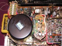
Sakis: Under the caps its basically the bottom plate. Nothing can go in there thicker than a sheet of paper.
But yes I suspect its under something. This pic I found on audiokarma. Mine, I have pulled that board on the caps off. But well, no room under that either. Wire chasing ... yes.
Nigel: Yes, like an anthill. Stare at it a few mins and you'd swear they are moving.
Under the fuse board is what someone suggested, I will get to it tonight. Hope ...
Cool.
Srinath.
Still eating 8 amp fuses.
I put new 8 amp fuses in and they last for ~1/2 a second. In that time it makes pretty loud noise and then nothing.
The safety relay clicks just fine.
With blown fuses it makes a bit of faint volume in the left channel and it has a lot of static.
The rest of the unit works just fine.
Does any one have any idea on this thing.
Thanks.
Srinath.
Last edited:
Would this work.
TYCO ELECTRONICS / POTTER & BRUMFIELD|W58-XB1A4A-15|CIRCUIT BREAKER, THERMAL, 1P, | Newark.com
Would I be able to wire that in so I dont have to replace fuses any time I power it up to test it ?
Is that dangerous ?
Thanks.
Srinath.
TYCO ELECTRONICS / POTTER & BRUMFIELD|W58-XB1A4A-15|CIRCUIT BREAKER, THERMAL, 1P, | Newark.com
Would I be able to wire that in so I dont have to replace fuses any time I power it up to test it ?
Is that dangerous ?
Thanks.
Srinath.
- Status
- This old topic is closed. If you want to reopen this topic, contact a moderator using the "Report Post" button.
- Home
- Amplifiers
- Solid State
- JVC JR s600 blows 8 amp fuses.