Hi - my first post - please be gentle,
I've been lurking reading your posts about the gainclone amps and will shortly be building an active four way system with crossovers for a stereo woofer and tweeter set up.
I've searched for relevant posts about VCA volume control. The opto-coupled system was interesting too.
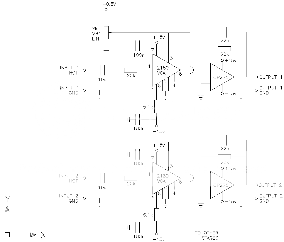
Attached is an image of what I hope could be an outline way of controlling the volume of any number of channels simultaneously.
There is a thread using the 2180 series VCA on a compressor unit - essentially I think I have gone for a boiled down version of that. Please read the diagram with reference to
http://www.thatcorp.com/datashts/2180data.pdf
All comments gratefully received.
Thanks for reading.
I've been lurking reading your posts about the gainclone amps and will shortly be building an active four way system with crossovers for a stereo woofer and tweeter set up.
I've searched for relevant posts about VCA volume control. The opto-coupled system was interesting too.
Attached is an image of what I hope could be an outline way of controlling the volume of any number of channels simultaneously.
There is a thread using the 2180 series VCA on a compressor unit - essentially I think I have gone for a boiled down version of that. Please read the diagram with reference to
http://www.thatcorp.com/datashts/2180data.pdf
All comments gratefully received.
Thanks for reading.
Member
Joined 2009
Paid Member
Hi Davelowe, welcome on board.
It looks an interesting option. I took a peak at the datasheet for that part and the specs look quite good indeed. They even show the harmonic distortion (FFT) instead of the nearly useless THD spec.
Some people around here are allergic to op-amps though")
Anyhow, if it's not a big expense against the budget you've allocated for this project you might like to build it and listen for yourself - it's advice you'll hear a lot and it's good advice.
For those allergic to op-amps you could consider using JFETs as volume control elements. They can have higher distortion but some people like their simplicity. I've no idea which approach is best. Using a FET as a Voltage Controlled Resistor
It looks an interesting option. I took a peak at the datasheet for that part and the specs look quite good indeed. They even show the harmonic distortion (FFT) instead of the nearly useless THD spec.
Some people around here are allergic to op-amps though
Anyhow, if it's not a big expense against the budget you've allocated for this project you might like to build it and listen for yourself - it's advice you'll hear a lot and it's good advice.
For those allergic to op-amps you could consider using JFETs as volume control elements. They can have higher distortion but some people like their simplicity. I've no idea which approach is best. Using a FET as a Voltage Controlled Resistor
Last edited:
I'm hoping to revive this thread because I'm interested in doing pretty much the same thing. (I'm actually planning to build a 4.1 chip-amp for my office / computer room.)
After looking at the schematic, I'm tempted to say it's missing a buffering op-amp on the control signal. THAT's tech note seems to suggest this is almost necessary (page 9 -- "the 2180 Series VCAs are designed to be operated with zero source impedance at pins 2 and 3") but warns against how many op-amps have considerable inductance at high frequencies. In this case, we're using an op-amp as a DC amplifier, so I don't think it's an issue, but their fix seems simple (series R + C.)
Now, I'm a complete newb to circuit design. I'm just at the "try to build something I found online" stage -- but I'm trying to understand. Can someone elaborate on how to create the control voltage? I'm stuck at the "?K" part.
I'm guessing Ohm's law has something to do with this.. but op-amp inputs are supposed to be ideally infinite impedance. So. I'm struggling with how to design an appropriate circuit for this. I assume it would look something like this?
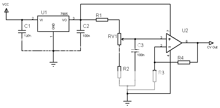
Hopefully I'm in the ballpark here. Here's the idea so far:
R1 - Drop the regulated 5V to something below 1V when combined with the resistance of RV1 (0 to whatever RV1 is).
R2 - To avoid shorting the VR's output to ground (maybe not necessary due to R1 ... or does this leg of the pot even need to be connected at all?)
R3 and R4 - Gain setting for the op-amp... maybe a better choice to use this to scale the voltage down rather than wasting it via R1.
Thoughts? Am I even close?
After looking at the schematic, I'm tempted to say it's missing a buffering op-amp on the control signal. THAT's tech note seems to suggest this is almost necessary (page 9 -- "the 2180 Series VCAs are designed to be operated with zero source impedance at pins 2 and 3") but warns against how many op-amps have considerable inductance at high frequencies. In this case, we're using an op-amp as a DC amplifier, so I don't think it's an issue, but their fix seems simple (series R + C.)
Now, I'm a complete newb to circuit design. I'm just at the "try to build something I found online" stage -- but I'm trying to understand. Can someone elaborate on how to create the control voltage? I'm stuck at the "?K" part.
I'm guessing Ohm's law has something to do with this.. but op-amp inputs are supposed to be ideally infinite impedance. So. I'm struggling with how to design an appropriate circuit for this. I assume it would look something like this?
Hopefully I'm in the ballpark here. Here's the idea so far:
R1 - Drop the regulated 5V to something below 1V when combined with the resistance of RV1 (0 to whatever RV1 is).
R2 - To avoid shorting the VR's output to ground (maybe not necessary due to R1 ... or does this leg of the pot even need to be connected at all?)
R3 and R4 - Gain setting for the op-amp... maybe a better choice to use this to scale the voltage down rather than wasting it via R1.
Thoughts? Am I even close?
- Status
- This old topic is closed. If you want to reopen this topic, contact a moderator using the "Report Post" button.