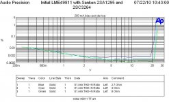
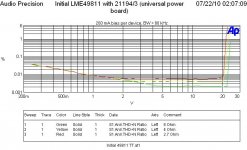
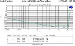
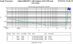
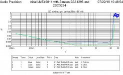
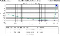
I evaluate performance of my LME49811 amp with several power BJTs. Three pairs have been evaluated. They are Sanken 2SA1295/C3264, ON Semi MJL21194/93 and NJL3281D/1302D. The bias is 200 mA per device. There are two-pair employed. The supply is +/- 40 V (660VA transformer, 30000 uF per rail). The drivers in all cases are MJL150034/35.
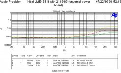
Based on the results, 2SA1295/C3264 and NJL3281/1302 offer comparable performance. NJL outperforms Sanken pair in low-freq region. 21194/93 pair has the lowest fT. This is probably the reason behind its higher THD in high-freq region.
Here are THD vs freq plots for various loads.
Based on the results, 2SA1295/C3264 and NJL3281/1302 offer comparable performance. NJL outperforms Sanken pair in low-freq region. 21194/93 pair has the lowest fT. This is probably the reason behind its higher THD in high-freq region.
Here are THD vs freq plots for various loads.
Attachments
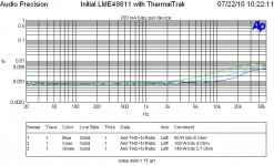

THD vs level for 1 kHz tone
Here are plots for THD vs level for 1 kHz for various loads.
This is interesting to see that the Sanken pair is not as good as the 21194/93 pair in this test. The former has better hfe vs Ic than the later. The later has the highest clipping level for 2.7 Ohm load.
Here are plots for THD vs level for 1 kHz for various loads.
This is interesting to see that the Sanken pair is not as good as the 21194/93 pair in this test. The former has better hfe vs Ic than the later. The later has the highest clipping level for 2.7 Ohm load.
Attachments
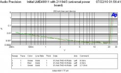
THD vs level for 10 kHz tone
Here a plots for THD vs level for 10 kHz.
21194/93 has the lowest clipping level for 4 Ohm load. This level is equal to that of 2.7 Ohm load. For the other two power BJTs, clipping level for 4 Ohm and 8 Ohm are identical.
THD for 21194/93 is flat from 5 V which indicates distortion limited performance. Sanken pair is more less the same, but with lower THD.
NJL performs the best in this test. The performance is still noise limited in high output level.
Attachments
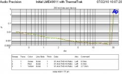
THD vs level for 20 kHz tone
Here are plots of THD vs level for 20 kHz.
Although 21194/93 is inferior to the others, the THD is still very low in common standard, < 0.01 % for 4 Ohm and 8 Ohm.
NJL and Sanken are below 0.01 % for all loads. NJL slightly outperforms Sanken in 4 Ohm and 8 Ohm cases.
Here are plots of THD vs level for 20 kHz.
Although 21194/93 is inferior to the others, the THD is still very low in common standard, < 0.01 % for 4 Ohm and 8 Ohm.
NJL and Sanken are below 0.01 % for all loads. NJL slightly outperforms Sanken in 4 Ohm and 8 Ohm cases.
Attachments
Good investigation. Thanks for publishing.
One parameter that is very valuable in a power amplifier system
is the gain of transistors used.
And when we have a look at those power transistors popular
we can see that they have a good high gain, hFE
An output stage with low current gain will put more load on the previous stage.
And so distortion increase.
We want light load.
This is also why triple darlington is used.
Such a stage is very easy to drive, due to the enormous current gain.
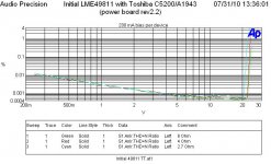
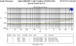
Toshiba 2SC5200/A1943
Here are performance plots for Toshiba 2SC5200/A1943 power BJTs. They are employed in many Hi-End power amps, e.g. Luxman M-800A.
Up to this point, NJL3281D/1302D are the best pair among the tested devices.
Here are performance plots for Toshiba 2SC5200/A1943 power BJTs. They are employed in many Hi-End power amps, e.g. Luxman M-800A.
Up to this point, NJL3281D/1302D are the best pair among the tested devices.
Attachments
Last edited:
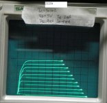
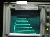
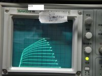
Ic vs Vce curves
We all knew that a real BJT behaves more like an ideal BJT when handling lower current. Ic/Vce curves given in the data sheet are always not very useful for a particular amp operating condition. For instance, such curves of MJL21194 and NJL3281 cover Ic over 10 A. At such high Ic, current gain has dropped substantially, and not likely the normal listening output power.
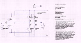
I measured the Ic/Vce curves of the above BJTs for lower Ic. The DUT has a heatsink (65 x 40 x 20 mm) and cooling fan to avoid over temperature. The setting for curve tracer is written on the white label (mA/div, V/div). Note Ib was 5 mA for MJL21194 whereas Ib was 2 mA for other BJTs. What can see all BJTs have Ic nearly independent to Vce (ideal transistor Ic/Vce curves) when Ic is less than 2.5 A and Vce = 5 V. These are the Ic and Vce levels for a two-pair output stage driving a load consisting of 2 uF // 6 Ohm as shown in the simulation mode below where supply rails is +/- 40 V. The BJTs are nearly "ideal".
If the load resistor is reduced to 2 Ohm, the peak Ic will be about 7.2 A with Vce = 3.2 V. Hence, we also need a set of higher current Ic/Vce curves. They will be shown in the new post.
We all knew that a real BJT behaves more like an ideal BJT when handling lower current. Ic/Vce curves given in the data sheet are always not very useful for a particular amp operating condition. For instance, such curves of MJL21194 and NJL3281 cover Ic over 10 A. At such high Ic, current gain has dropped substantially, and not likely the normal listening output power.
I measured the Ic/Vce curves of the above BJTs for lower Ic. The DUT has a heatsink (65 x 40 x 20 mm) and cooling fan to avoid over temperature. The setting for curve tracer is written on the white label (mA/div, V/div). Note Ib was 5 mA for MJL21194 whereas Ib was 2 mA for other BJTs. What can see all BJTs have Ic nearly independent to Vce (ideal transistor Ic/Vce curves) when Ic is less than 2.5 A and Vce = 5 V. These are the Ic and Vce levels for a two-pair output stage driving a load consisting of 2 uF // 6 Ohm as shown in the simulation mode below where supply rails is +/- 40 V. The BJTs are nearly "ideal".
If the load resistor is reduced to 2 Ohm, the peak Ic will be about 7.2 A with Vce = 3.2 V. Hence, we also need a set of higher current Ic/Vce curves. They will be shown in the new post.
Attachments
Last edited:
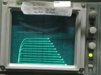
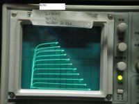
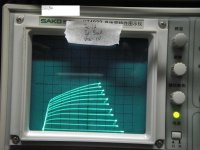
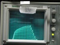
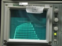
Ic vs Vce curves (cont.)
Here are higher current Ic/Vce curves. Although 21194 has a lower current gain, it seems to behave better in higher current compared to others. When Ic = 5 A and Vce = 5 V, it has a more flat Ic-Vce curve than that of the others. This may answer why output stage using 21194/93 results in a higher clipping level for heavy loads.
Here are higher current Ic/Vce curves. Although 21194 has a lower current gain, it seems to behave better in higher current compared to others. When Ic = 5 A and Vce = 5 V, it has a more flat Ic-Vce curve than that of the others. This may answer why output stage using 21194/93 results in a higher clipping level for heavy loads.
Attachments
Last edited:
")
Thanks Greg.
If we can parallel two more pairs, we should be able to get higher clipping levels. The new clipping levels for NJL, 2SC may be identical (slightly higher) than that of two-pair 21194/93. The new clipping level for 21194/93 may be two volts from the supply rail.
If we can parallel two more pairs, we should be able to get higher clipping levels. The new clipping levels for NJL, 2SC may be identical (slightly higher) than that of two-pair 21194/93. The new clipping level for 21194/93 may be two volts from the supply rail.
Last edited:
I measured the Ic/Vce curves of the above BJTs for lower Ic. The DUT has a heatsink (65 x 40 x 20 mm) and cooling fan to avoid over temperature. The setting for curve tracer is written on the white label (mA/div, V/div). Note Ib was 5 mA for MJL21194 whereas Ib was 2 mA for other BJTs. What can see all BJTs have Ic nearly independent to Vce (ideal transistor Ic/Vce curves) when Ic is less than 2.5 A and Vce = 5 V. These are the Ic and Vce levels for a two-pair output stage driving a load consisting of 2 uF // 6 Ohm as shown in the simulation mode below where supply rails is +/- 40 V. The BJTs are nearly "ideal".
From the curves, we can see that the clipping levels (Ic = 2.5 A) for 2SC and NJL are about 10 volts from supply rails. On the other hand, 21193/93 is about 5 V.
Douglas Self has also written about this and he coined the term 'load-invariant power amp' IIRC. Basically he looked at the increased linearity with more output pairs.
One way to look at that is that if you double the output pair, it LOOKS for each pair as if the load has doubled from say 8 ohms to 16 ohms as the required Ic for one pair for a certain output level is halved.
If you also want to keep the advantage of lower Vce you would tend to speakers with low impedance (like 4 ohms drivers) for low output signal for a certain sound level, coupled with multiple output pairs.
jd
One way to look at that is that if you double the output pair, it LOOKS for each pair as if the load has doubled from say 8 ohms to 16 ohms as the required Ic for one pair for a certain output level is halved.
Right.
That s why i use at least two power devices pairs for a 50W/8R amp.
The only drawback is power dissipation at iddle, but since most designs
are AB class, it doesn t really matter.
- Status
- This old topic is closed. If you want to reopen this topic, contact a moderator using the "Report Post" button.
- Home
- Amplifiers
- Solid State
- Comparing Power BJTs (Sanken, ON Semi, ...)