Hello,
I am renovating P/L 700 II with complementary output topology. More historical and current status info is here: Any Phase Linear Experts out there? - Page 12 - AudioKarma.org Home Audio Stereo Discussion Forums.
While following the service manual test step 6-1.3 I came across a problem of shorted/v.low resistance reading - 2-3ohms - between upper pole common collector buss and any of the emitter contacts on TO-3 sockets, unlike it is for the lower pole (the reading is ca. 700+ ohms) and the whole left channel (upper+lower poles) similar measurements.
All output xtrs and drivers are taken out. All xtrs and diodes on PL36 checked 'in circuit' - no shorted one found.
One of suspects is D107, but not sure where it is located as my manual copy is very poor where it comes to parts location.
Any help/advice please?
Many tx!
I just finished a complete rebuild of a full complimentary 400II last month. It was bought off of fleabay complete with counterfeit output transistors and lots of other crappy work. I replaced all electrolytics, semiconductors, bad resistors, and circuit board hook up wiring. This particular amp had NO flyback diodes, the ones you are looking for, and NO .33uf decoupling capacitors and there was no sign of them ever being there. Both are supposed to be soldered to the small three lug terminal strips mounted between the rows of transistors. If you cannot find any diodes in the point to point wiring around the output stage they were probably never installed, the amp will work fine without them in normal situations. So if you cannot find them you have other problems regarding the low resistance readings you are experiencing.
Craig
Craig
Last edited:
Check if the mica isolators of the outputs are well seated.
An easy way of fault-finding is to loosen the screws of the TO-3s a bit, one by one, keeping one eye on the ohm meter.
OP indicates that the output transistors are not currently installed. Schematic of output section would be helpful.
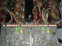
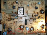
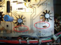
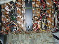
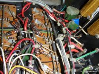
Thank you Craig, that's is probably the case. Serial number is 7A12070, there was a slightly different PL36 installed (see pictures). For sure no sign of flyback diodes in the place you said, but the decoupling caps are there. Which all means even more complicated reason to be found... I will measure PL36 resistors and see if any of them is drifted. One more difference to what I saw so far in P/L gears is the bias transistor on the right channel, which is now BD139, mounted with a screw on a silicon isolator where usually was 2N3404. I checked it however if shorted - seems to be OK ... What else you think can cause bad readings?This particular amp had NO flyback diodes, the ones you are looking for, and NO .33uf decoupling capacitors and there was no sign of them ever being there. Both are supposed to be soldered to the small three lug terminal strips mounted between the rows of transistors. If you cannot find any diodes in the point to point wiring around the output stage they were probably never installed, the amp will work fine without them in normal situations. So if you cannot find them you have other problems regarding the low resistance readings you are experiencing.
Przem
Attachments
OP indicates that the output transistors are not currently installed. Schematic of output section would be helpful.
Yes Netlist, Kevinkr is right. They are all out for the moment as anyway they will be replaced with MJ2119* (NPN/PNP) and for initializing the gear after repairs I wanted to have only drivers in. Besides, the mess with thermal compound called for careful cleaning of radiators.
Here are the schematics attached. Thank you for advice!
Attachments
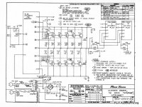
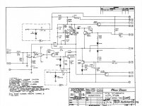
Here are the schematics attached. Thank you for advice!
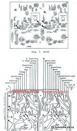
One more drawing with PL36 quasi-comp wiring for comparison. Connections numbering is in line with P/L 700 II service manual schematics.
Are the readings low in both directions regarding how you connect your meter?
Yes Craig, they are low either way. I was just checking more things and I also have shorted circuit readings between collector and base bus bars... Q201 to be inspected once more - I guess... Maybe I should desolder the whole PL36 to eliminate sockets isolation issue?
Tx for further supporting.
Since the 400 I rebuilt had fake transistors thru out I just shotgunned all of the semis, except the VI limiters. I used 2N3440 and 2N5416 for the VAS and predrivers. There are probably others you could use but those seem to be a common replacement for the 40327 and MM4003.
Craig
Craig
Q201 to be inspected once more - I guess...
Well, some more indications coming in after the predriver transistors measurements: Q101 vs. Q201 resistance readings in circuit gave different results: for Q201 E-C is 199 ohms both ways, while for Q101 E-C is 890+/1200+ohms depending on the meter polarity. A new replacement candidate?
Things get more complicated:
Any additional advice is very much welcome!
- Q201 2N3440 removed (was OK) - still 2-3 ohms between collector bus / emitters and the same for collector / base bus bars.
- orange (11), brown (9), blue (13) and multicolor (8) desoldered - wiring from PL36 to output bars of upper pole, right channel - and no change in readings
- C110 decoupling cap desoldered - no change again.
Any additional advice is very much welcome!
Ufff, problem identified: some tiny drop of cold solder in a very nasty place to spot, creating a short circuit between collector bus bar and that output emitter.
Back to normal readings")
Many thanks for all the support!
I will share my project progress when ready...
Regards
Back to normal readings
Many thanks for all the support!
I will share my project progress when ready...
Regards
Please do, I promise to read your posts a little more attentive next time.
/Hugo
Hello Hugo, it's promised then. World Cup has its own rights
. Cheers, PrzemPhase Linear 700 Series II - restoration guidelines
Before sharing the progress and results of my current Phase Linear renovation project let me post here a wrap-up of many valuable ‘lessons learned’ gathered from various DYI and Audiokarma threads for those who wish and can restore their Phase Linear 700 series II amps. Originally I posted such list on Audiokarma.org, but here is reedited version with some new thoughts embedded . These are all key points written in one place for possible further use, thanks to very useful contribution of many experts here and Phase Linear enthusiasts over the last years!
So, the main purpose of the list below is to help in planning and performing the restoration of 30+ years old Phase Linear 700 Series II amplifier (P/L700II), and certainly not to re-engineer the gear. Replacing a vast number of components, that were working well so far and are not specifically exposed to aging, is not recommended. No doubt however that a temptation to implement some advisable upgrades is in everyone of us. After all you decide at your own risk …
GENERAL RULE: Use extreme caution while performing any replacements/upgrades due hazardous voltage presence in P/L700II power amplifier. Be sure that before starting any replacements the line cord is unplugged and power supply caps are discharged. Strictly follow ALL check-up and repair procedures as written in P/L700II Service Manual and subsequent service bulletins. Wear safety glasses while taking data from powered circuits and soldering.
Driver board PL36
- P/L700II driver board (PL36) requires some closer attention. There are components that over last decades could loose resistance /capacitance desired characteristics or get open, even impacting other elements, not to mention about shorted diodes or signal transistors. Testing 'in circuit' as stated in the service manual is mandatory the very first step. I know many people who anyway replace all diodes and transistors from the driver board 'en block' - mainly if restoring unknown gear with visible badly performed repairs in the past. Resistor candidates to consider for replacement, as they may drift from heat and age, are the following:
- R1, R2 = 7.5K/5W 5% (these dropper resistors get so hot to even discolor the PCB card and affect nearby parts as well),
- R101 = 7.5K/2W 5% (applicable per both channels),
- R103 = 2.7K/0.5W 5% (applicable per both channels),
- All power outputs emitter resistors = 0,33Ohm/2W (if you replace them, pick high grade with 1% tolerance 3-5W, coated wirewounds are nice).
- Capacitors to cure possible oscillations, usually after replacement of power outputs: 22~47pF caps usually work well to damp out any such tendency (see specific P/L service bulletin on the issue). The factory recommended 150~270pF value might be too high, and can cause high frequency slewing at high output power. Ceramic or silver mica types are recommended with at least a 100-Volt rating.
- Another point to consider is to replace input coupling caps (.47uF) with a high grade equivalents - worth of experimenting (limited space as they are mounted closely to RCA sockets).
- All electrolytic caps replacement is highly advisable. Try to stick to high class brands designed for audio applications (e.g. Panasonic FC, Nichicom KZ, Rubycon ZA). No need to exaggerate though - please bear in mind that Phase Linear power amps were direct coupled and have no electrolytic caps in the signal path. So the replacement is a rather a precaution to avoid caps aging problem in the power supply, feedback network and bootstrap circuit.
- The Op-Amp IC LF356 replacement with LF351 was recommended by the factory, so is the replacement of R1, R2 from 2.4K/5W to 7.5K/5W (the LF351 op-amp has better specs and helps with turn on/off thump). I don’t want to open a separate debate on whether LF351 is fine for front-end applications or not, in view of many options available these days. The op-amp in the P/L design had one purpose: to provide high gain and it was used to replace a traditional differential input pair - much more refined solution known from P/L 400-700 Series I. This had few advantages back in the 70's: all the transistors inside the op-amp could be closely matched (important for a differential amp) and production / testing was more efficient since matching of transistors was no longer necessary. LF351 is not at all a bad op-amp (in later complementary models there were also TL071P Low Noise used as the op-amp). So, you may leave it as is. However, for All who like experiments the use of BB OPA134 op-amp as direct replacement to LF351 might be sound quality beneficial upgrade.
- Regardless whether you stay with LF351 or not, there are some common practices you may want to consider for the op-amp working conditions improvement. First is to add decoupling 0,1uF (e.g. per 100V) high grade film type cap on the +/- 15V rail supply and mounted directly on the supply pins for each op-amp (diagram here Any Phase Linear Experts out there? - Page 5 - AudioKarma.org Home Audio Stereo Discussion Forums). The solution helps in removing power supply noise and possible distortions at high frequency. Second would be to add 4,7uF/35V electrolytic cap ('reservoir') in parallel to each D1, D2 Zener diode. Be careful though - too much capacitance increases the turn-on thump.
- Bias transistors 2N3404, located in-between power transistor banks, are obsolete. Two options that I saw for considerations: replacement of 2N3403 with TN6705A with reused “P” type heatsink and pinouts connection inverted (CBE) and even better – with NTE192A, already in TO92HS type package and compatible pinouts (BCE).
- Final review of the PCB card from the traces side is maybe a simple advice, but very important at the same time. Apparently over time the PCB material gets more ‘fatigue’ and you need to re-solder anything that looks questionable. Cold/open solders are most time consuming cause for the amp malfunctions to find.
- Outputs and drivers should be reinstalled even if not destroyed. The reason are aged thermal compound or rubber insulators causing failures in time when overheated. If the amp had silicon pads on the outputs always get new ones - never reuse them! Don't over-tighten while mounting transistors. If you use mica insulators as preference, go easy with term compound grease. Keep it out of the sockets. Heat sink plates must be well cleaned before re-installation of outputs and drivers.
- Following P/L service bulletins, output transistors in each channel should ALL be of the same type (e.g. MJ15024 or MJ21196 for quasi-comp. stage, or MJ15024/25 - MJ21196/95 respectively for fully comp. stage). MJ2119* are probably today’s most advanced high power TO-3 outputs and have higher SOA than MJ150**. In P/L700II fully complementary amp, the drivers and output transistors are the same. For example – the driver for the MJ15024 output transistors is a MJ15024. Same comment for the MJ15025 (PNP match for the MJ15024). In other words DO NOT mix different types of output transistors in a single channel. The previous statement is very important when doing service or repair work – not only with P/L equipment, but any kind / brand of amplifier. In P/L700II quasi complementary amp there are installed obsolete RCA410 as drivers. Leave them, if not shorted, for better stability and sound (subjective impression). Last but not least, avoid buying the output transistors from unknown sources, counterfeited ones are often found. They won’t be of any use in P/L power amps’ severe working conditions.
- There is an issue here, known to all P/L users. In P/L 700II amp the RCA input ground is correctly tied to the input ground of the amplifier's input circuits. Then the right channel's speaker ground is directly tied to the RCA ground... So ground current flowing into the right channel speaker ground is injected into the 'quiet' input ground (unwanted loop deteriorating the sound). Grounding is critical to both stability, measured performance and the amp sound quality. Star topology should be observed. At least one ground wiring should be added between a solid copper bare inside your amp and the common point on the power supply caps. Here are the most common problems and remedies:
- Issue #1: RCA input ground tied to the input ground of the amp input circuits (not a star topology). Solution: Leave it as is.
- Issue #2: Speaker terminals ground tied to the RCA and driver board input ground. Solution: Cut the grounding connection of speaker terminals, draw instead a new grounding wire to the PS caps common point clad. Move the driver board ground to the power supply ground, at the junction of the two PS caps.
- Issue #3: 230VAC, B+/- DC and low level audio wiring run in a bundle all together. Solution: Unbundle all the leads carrying AC, DC and audio. Shorten the DC power leads by directly routing them to the capacitors from the output stage. Shorten the ground leads in the same manner. Reroute the audio wiring from the rear apron directly to the front panel and add shielding on the input wires between RCA sockets and PL36 board.
- To conclude on re-wiring, a piece of electromechanical advice: replace all RCA inputs and speakers posts for something 'more sound neutral' and solid than it was 30 years ago… A variety of solutions can be found in other DIY threads. Also don’t forget about the power cord – better to replace the old one if suspected condition. It should be non-polarized and not wall socket grounded (even for EU standards) – otherwise very likely hum problems appear. Keep the 'earth ground' connected closely to your source of music (CD/DAC/Pre-amp).
- Power caps are absolutely worth of replacing. They also strongly influence the sound when got dried over the years. Sometimes they may well become a source of hum. With the new ones go for twice the capacity than original - ca. 20.000uF @100V at minimum - you can find per 160V at small price difference = better (The originals were 9800uf @100V and they run right around 100V. With caps you buy today you don't get the headroom like you did 20 years ago...). The power supply caps testing: check if they have less than a few hundred mV of ripple at idle, at full load it will be slightly over 1V. Don’t buy power caps older than 3-5 years of shelf storage, if you don’t have time for reformatting them. Watch the cap size to avoid additional mounting problems. Before you begin, remember to discharge the power caps (a resistor 10-25 Ohm/10W would help)!
- If you increase the power cap capacitance from original value of 9.800uF to say 20.000uF, you need to take into account the higher stress on your bridge rectifier. Some P/L owners decided therefore to upgrade it for >35A/400V units. In addition bypassing each diode by 0.01uF/1000V cap (ceramic or mylar HQ) will help to cure against RF unwanted interferences. BTW, you need to check the presence of C112=0.22uF/400V as no longer needed. Bypassing filter caps with two mylar caps 0.1-1uF/600V can be considered if you go for larger power capacitors. It will improve the ESR at higher frequencies. For 20.000uF cap, with low ESR, ‘computer high grade’ type, etc., etc. - you may not bother, probably.
- When you performed all the upgrades, installing the output protection circuit is to be seriously considered to eventually save your precious loudspeakers... There are few options for P/L700II to follow - just Google the topic. But one common mistake here is to forget about reconnecting the RF Zobel network (C108 & R135) from speakers’ terminals to the protection unit inputs. You will experience oscillation problems if you forget the precaution.
- Volume pots can be sometimes in a really bad shape – replace them with low noise equivalents, watch out for dimensions and axis profile.
- For powering up, before the check-up procedure starts, or/and for performed modifications testing, use light bulb test set (http://www.audiokarma.org/forums/sho...d.php?t=187673). Start with a 40 or 60 Watt bulb. Step up to 100 Watt or 200 Watt as your confidence builds. You can't have a load connected when you use the bulb. The amp puts out several volts DC as it starts up. If a load is attached, the bulb limits the current, as it is supposed to, and the AC input never gets above 30-40 volts. Using variac and bulb test circuit is probably the safest. Variacs do not limit the current and may cause burned all the output transistors (painful when you just replaced them…). If you still want to use the variac only, change AGC fuses to much smaller values to control excessive current.
- In the end bias setting is always needed. See related procedure in the P/L700II service manual. Here is a short summary - not to forget about the step. So, when all the changes to your amp are finally done, use the bulb testing device to start the amp with no I/O connections. When successful, use a voltmeter to measure Voltage across the zener diodes. You should see +/- 15 VDC. Typical is around 14.5 VDC. Then with full input voltage check for about 300~350 mV DC on the 10 Ohm/0.5W resistors on the output buss (R109). Adjust the pot (R107) for the corresponding channel as needed. Recheck in ten minutes. Verify if less than 30 mV. Be careful when taking data. A slip of the probe will cause major damage. Insulate the probe tip with tape or heat-shrink.
starting up Phase Linear 700 Series II after repairs
Hello,
Tried to initialize the amp after a major restoration project. Here is the list of what was done:
According to service manual there are two things to be checked when the line fuse is blown: bridge rectifier and power caps. Didn't check the rectifier at higher voltage but don't think there is an issue there (will double check though). PS caps were carefully formatted before installation. Just in case I re-tested power transistors and drivers after the initial start-up. They are all OK.
Let me then ask more experienced Experts here, hat practical steps to be taken (at what sequence) to diagnose reasons of excessive current drawing by this amp? PL36 is suspect - I didn't replace any transistors there, only measured for shorted ones 'in circuit'.
Many thanks for advice!
Hello,
Tried to initialize the amp after a major restoration project. Here is the list of what was done:
- Complete rewiring: separating/rebinding AC, DC, audio signal (and adding shielding between RCA inputs and PL-36 PCB);
- RCA input posts replaced with HQ version
- Speaker posts replaced heavy duty type
- Volume pots replaced with BLUE ALPS RK27
- All emitter resistors replaced with 3W 5% matched new ones (among old resistors three were found completely drifted)
- Input coupling caps (.47uF) replaced with HQ V-Caps
- Four electrolytic caps on PL36 replaced with new Nichicon high grade
- AC cord replaced (two-prong type maintained)
- Power Supply electrolytic caps replaced (11.000uF / 100V)
- 7,5K 5W and 7,5K 3W resistors replaced with matched ones (old had too significant resistance difference)
- TL071 op-amp is replaced with BB equivalent OPA134
- All previous outputs taken out, radiators cleaned from tons of thermal compound (several transistors had only the compound between mica and the radiator) and new drivers + outputs were put in place - MJ21195/6 type
- Speaker DC protection/delay PCBs installed and wired (to be activated at the very end restoration process).
According to service manual there are two things to be checked when the line fuse is blown: bridge rectifier and power caps. Didn't check the rectifier at higher voltage but don't think there is an issue there (will double check though). PS caps were carefully formatted before installation. Just in case I re-tested power transistors and drivers after the initial start-up. They are all OK.
Let me then ask more experienced Experts here, hat practical steps to be taken (at what sequence) to diagnose reasons of excessive current drawing by this amp? PL36 is suspect - I didn't replace any transistors there, only measured for shorted ones 'in circuit'.
Many thanks for advice!
Last edited:
Recheck all of the wiring you replaced, make sure all of NPNs and PNPs are in the correct locations, diodes in correctly. On a 400 (not sure on the 700) the DC fuses supply only the output stages so if those are removed and the Variac can be turned up without any problems you'll know the problem is in the output stage. It'll be something stupid, it always is. Oh did I do that? If I remember correctly the 700 has separate DC fuses for each channel.
Craig
Craig
- Status
- This old topic is closed. If you want to reopen this topic, contact a moderator using the "Report Post" button.
- Home
- Amplifiers
- Solid State
- Phase Linear 700 series II restoration