Hi,
I am a little confused about one of the connections to this kit. On the ebay page:
eBay.ph: Speaker protection circuit stereo kit 30A protection ! (item 320496814744 end time Aug 02, 2010 00:32:49 PHT)
It shows a connector with "Power Amp Output Connection"
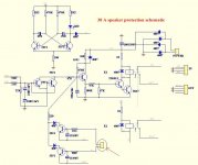
I also attach the schematic with the connector circled.
Initially, I thought that this required connection to the 'output' of the amplifier - but this cant be the case, why would they not do this routing on the board?
Can anyone shed some light on the purpose of this connector?
Many thanks for your help!
Cheers,
Andy
I am a little confused about one of the connections to this kit. On the ebay page:
eBay.ph: Speaker protection circuit stereo kit 30A protection ! (item 320496814744 end time Aug 02, 2010 00:32:49 PHT)
It shows a connector with "Power Amp Output Connection"
I also attach the schematic with the connector circled.
Initially, I thought that this required connection to the 'output' of the amplifier - but this cant be the case, why would they not do this routing on the board?
Can anyone shed some light on the purpose of this connector?
Many thanks for your help!
Cheers,
Andy
Attachments
I have put a copy of the schematic on the web - hopefully it is more easy to read:
http://img682.imageshack.us/img682/8708/spkprotection30a.jpg
http://img682.imageshack.us/img682/8708/spkprotection30a.jpg
An externally hosted image should be here but it was not working when we last tested it.
Hi Andy
I see the difficulty you are having when I compare this circuit (which is sketchy to say the least) with Silicon Chip Magazine's newest universal design. Don't discount the probability that this circuit may have to work in tandem with similar circuitry, a headphone switching arrangement, fuse or even crowbar circuit. With 30 amp rating, it's bound to attract pro. attention where such features are common. Consequently, there will be a need to sense faults upstream of these circuits and so the separate leads.
There are two other sensor circuits shown there, probably a thermal switch (lower) and a muting connection to a 12V control circuit. Are they real or just suggested to add this feature? If they are onboard, a connection to a sense point or 12V circuit might help them to work.
I suggest you check for continuity between the input points,the relay contacts and the 22k sense resistors anyway and let logic take its course. If no connection, you will have to add it, here or upstream as you prefer.
Last edited:
The overload protection circuit will react when the voltage over the emitter resistor is above 0.5-0.6Volts. So if the emitter resistor is 0.22 ohms, it will be at 0.5/0.22 = 2.2 ampere, or 39Watt peak (19,5W rms) in 8 ohms.
To increase the allowed output current, add a resistor-divider between the emitter-resistor and the sensor input.
To increase the allowed output current, add a resistor-divider between the emitter-resistor and the sensor input.
Hi,
I am a little confused about one of the connections to this kit. On the ebay page:
eBay.ph: Speaker protection circuit stereo kit 30A protection ! (item 320496814744 end time Aug 02, 2010 00:32:49 PHT)
It shows a connector with "Power Amp Output Connection"
I also attach the schematic with the connector circled.
Initially, I thought that this required connection to the 'output' of the amplifier - but this cant be the case, why would they not do this routing on the board?
Can anyone shed some light on the purpose of this connector?
Many thanks for your help!
Cheers,
Andy
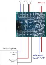
Anyone know what gets wired to the "L", "R"?
Attachments
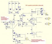
That thermal overload device identified by Enrik (post 8) has to connect somewhere!
Click on that thumbnail. See the four yellow blocks, actually connectors ?
...We just can't positively identify what the device is; From the schematic, the arrow
suggests it might be a another subcircuit but practically it is probably just a thermistor,
thermal switch or other device.
Omitting that whole circuit connection should not affect normal operation as a DC sensor and delay.
Last edited:

Is the notation on the circuit and circuit operation #8 and #9 not clear?
According to Nrik, L(eft) and R(ight) leads connect to the top (emitter side)
of the positive emitter resistors in your output stage - L and R channels respectively.
You must locate and make this connection yourself. The other side of the resistor is
the output (+) which is already connected.
It seems awkward but if you want a working safety overload switch, it must be
adjusted to the amp and transistor SOA characteristics anyway. This is not a 5
min. task unless you undershoot with a wide safety margin and just hope for the best.
How are these terminals get wired?
What is their purpose?
I have assembled one of these kits and posed the same question to the supplier.
The terminals are 'specifically for solid-state push pull amplifier that has emitter degeneration resistors. Since not all amplifiers are of this architecture so we usually ask users to ignore it.'
I suggested to the supplier that the kit instructions include this information.
Attachments
I have assembled one of these kits and posed the same question to the supplier.
The terminals are 'specifically for solid-state push pull amplifier that has emitter degeneration resistors. Since not all amplifiers are of this architecture so we usually ask users to ignore it.'
I suggested to the supplier that the kit instructions include this information.
so what do you think of this kit so far?
are they worth buying, Ebay, has a lot of them , Ebay link of one of them (30amp)
eBay - New & used electronics, cars, apparel, collectibles, sporting goods & more at low prices
I also been looking at the this one (15amp)
eBay - New & used electronics, cars, apparel, collectibles, sporting goods & more at low prices
Elliott Sound Products (Amp?)
Loudspeaker Protection and Muting
looks like the K4701b are harder to find now (10amp)
I'm thinking of ordering some for my Phace Linear Amps 700 II or 400II
which can have thums when turing on & off, I like the 30amp rating
so what do people think of these newer kits?
- Status
- This old topic is closed. If you want to reopen this topic, contact a moderator using the "Report Post" button.
- Home
- Amplifiers
- Solid State
- Jims Audio - 30A Speaker Protection Kit