Hi Per!
if i remember right, my own amp which (was a mind offspring of the Alexander).. i have set up the current in the input stage.
The reason was that i could se a small difference on the slewrate.
With a current of 1 mA the input bjt will have a re = ~ 25Ohm.
by setting the current 5 times higher it will slew better.
But have to take into consideration that the BJT was low beta types (2n3904/06).
I hope this was what you were looking for.
I have not run any sim on this.
Sonny
Noise
The noise curves are a function of the source impedance and collector current of the transistor. Its like a "u". So you will have to use a device that is suited for your source impedance for the lowest noise performance. A good example is the Phono cartridge . MM and MC need different input devices for lowest noise performance. I think lower source impedance usually have higher collector currents. The curve is a U and so the Noise Figure is lowest only in a small band . My memory is rusty. I will dig out the curves and put up a clearer post.
Check out the noise figure curves for the BC549 or similar and you can see what I mean.
Guys, I know about noise figures in general. I have dived deep into it but the question now is more like if it's a difference in performance with different currents. Yes, obviously, but how much?
One parameter is critical and that is Rbe f the input transistors, should be as low as possible => high current
One parameter is critical and that is Rbe f the input transistors, should be as low as possible => high current
I got inspired to make one amp (headphone for starters) with a classic current feedback topology like in integrated ones. Just for fun and for pure technical reasons only.
Right now I'm just interested in the theory (mirrored over to real thing amp), don't care how good it sounds.
Right now I'm just interested in the theory (mirrored over to real thing amp), don't care how good it sounds.
Hi Per,
I have a complete SPICE simulation of a power amplifier circuit using that topology with the freeware LTSpice from Linear Technology. If you like, I can provide you with all files and models needed to run it, or I can try some things in the simulation if you provide some specific suggestions. I'm at work now, and won't be home for another 11 hours or so. I can provide more specific information then (schematics, etc.).
I have a complete SPICE simulation of a power amplifier circuit using that topology with the freeware LTSpice from Linear Technology. If you like, I can provide you with all files and models needed to run it, or I can try some things in the simulation if you provide some specific suggestions. I'm at work now, and won't be home for another 11 hours or so. I can provide more specific information then (schematics, etc.).
Maybe I have to download LTSpice but it have to wait until Monday (just Mac at homeandy_c said:Hi Per,
I have a complete SPICE simulation of a power amplifier circuit using that topology with the freeware LTSpice from Linear Technology. If you like, I can provide you with all files and models needed to run it, or I can try some things in the simulation if you provide some specific suggestions. I'm at work now, and won't be home for another 11 hours or so. I can provide more specific information then (schematics, etc.).
") ). Do I have regular parts as BC5xx and some common BD139 like parts?
). Do I have regular parts as BC5xx and some common BD139 like parts?Maybe this shall be my first SPICE project? I became a little bit burned when a mate of mine use a SPICE simulation of his oscilloscope amp (YES, he built a 2" oscillscope, with batteries!!!) and the real world was very cruel to him. He had a long print which came out from a VAX computer. But I suppose the SPICE models have been developed and also the computers....

I notice also that some people (at headwize, heead-fi) elevate current feedback near nirvana. Have you checked Mr. Meier and his extreme opamp-amp with loads of CFA opamps?Jocko Homo said:I messed with that topology years ago. I didn't remember it having any noticeable impact.
http://home.t-online.de/home/meier-audio/prepoweramp.htm
Rolling your own......
If you plan to make one from scratch for the learning experience......good idea, BTW, then you should consider either using things like MAT-04 or the like.....or put some degeneration resisitors in the emitter legs of the current mirrors. Other wise, thermal effects will cause it to go nuts.
The inverting configuration is easier to work with.
Jocko
Resistor values sound ok. Suggested bias level also ok. Problem is stray capacitance at the nodes. Keep the resistor values for the feedback network low. (I assumne that you know this already, but just in case it slipped your memeory.....it happens to those of us who really don't understand what we are doing.)
Have fun.
Jocko
Have fun.
Jocko
Hello Per-Anders,
Classic Hiraga 20W amp has 600-650uA in the first (Q3, Q4) and a bit more than 1mA in the second part (Q1, Q2) of the diamond transistor. However it is entirely biased by resistors.
Btw, opamps (LM6171) that Meier uses are not CFAs. But approach is interesting anyway.
Pedja
Classic Hiraga 20W amp has 600-650uA in the first (Q3, Q4) and a bit more than 1mA in the second part (Q1, Q2) of the diamond transistor. However it is entirely biased by resistors.
Btw, opamps (LM6171) that Meier uses are not CFAs. But approach is interesting anyway.
Pedja
Hi Per-Anders,
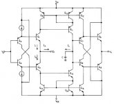
Well, I realized that my power amp design was overkill for your application. It is designed around +/- 90 V rails, so it has the complications of cascoding for high voltage and high current output stage with many devices (a Holton rip-off). I've attached a schematic from LTSpice below.
Regarding slew rate, since the current for charging the compensation caps originates in the output stage, the slew rate should be nearly independent of the input stage bias current. You can see input stage current limiting in the schematic below. This stage could otherwise be blown out during slew rate testing, or clipping with low-frequency signals when the Baker clamp kicks in. It sounds like you're quite familiar with noise considerations, so there's nothing new in that regard.
At one time, I had thought of using the HA-5002 for the complementary buffers of a design similar to what you posted. It has separate plus and minus supplies for the two stages of emitter followers (four supply pins total), so you can pick off the exact point you need to hook up the current mirror. But it looks like the output stage runs at about 4-5 mA, a bit high, and the bandwidth is a bit higher than I'm comfortable with. It does put out 200mA, which is pretty cool. And it runs class A, which is a plus. I had even thought of using it as the input stage for my power amp. That high bias current scares me off though
As far as parts, I suspect that what's easy to obtain in your country may be difficult to obtain in mine, and vice versa. Judging by your site, you're a way more advanced builder than I am, so any practical information is something I'd be better off getting from you rather than the other way around. The last DIY project I did was a Leach amp... in 1979! At the places I worked before switching over to software, technicians did all the construction. But I'm getting back in the swing of things, thanks to this site and the people who post here.
Attachments
I got confused by this. I had to check the datasheet. The LM6171 is infact a CFA inside but disguised as a normal opamp and this is accomplished by adding a buffer to the inverting input.Pedja said:Btw, opamps (LM6171) that Meier uses are not CFAs. But approach is interesting anyway.
You don't know me! Overkill is my trademarkandy_c said:Hi Per-Anders,
Well, I realized that my power amp design was overkill for your application.
Anyway, nice design but it never left the computer?
If you would send me your similation file I'd appreciate it.
I notice also that CFA is a rather unknown topic for most DIY's, including myself. In my professional life I had never been forced to use CFA's.
peranders said:
Anyway, nice design but it never left the computer?
I ended up abandoning that design. I was trying to produce a square wave at full output into a 2 uF load with no ringing or overshoot, using no output inductor. To get good stability with this load, I had to reduce the unity loop gain frequency quite a bit. Then there was not much feedback left at 20 kHz. A Fourier analysis using transient and sine wave input with SPICE showed the third harmonic at a disappointing 1 percent at 20 kHz, full power. This was not in the output stage, but somewhere in the input stage or current mirror (hard to separate with CFAs). I couldn't improve it. 1 percent is too much for a solid state amp! I ended up switching to a voltage feedback design, using some of the Douglas Self techniques to reduce the amp's open-loop distortion, but still keeping the global feedback low. I am still modifying the design, but so far I've gotten a 20x improvement in the computed third harmonic of 20 kHz, and the simulated square wave respoinse into 2 uF looks clean.
Then after that, I can buy a scope, DVM, drill press,....
If you would send me your similation file I'd appreciate it.
Okay. I found a simulation I've done of exactly the topology you posted. Maybe I'll send you that one? The power amp I posted contains devices that aren't in the standard LTSpice installation, so you'd have to install these first. But the simpler simulation uses only standard devices, so that's better I think.
I notice also that CFA is a rather unknown topic for most DIY's, including myself. In my professional life I had never been forced to use CFA's.
Before changing over to software, I used to do radar signal processing. We used CFAs quite a bit there. Lots of fast analog pulses to process in that application. I used to think that CFAs were the ulitmate, that audio designers were just plain stupid to not use that topology everywhere. But after doing quite a few simulations and thinking about the problems much more carefully, I have completely changed my tune on that.
- Status
- This old topic is closed. If you want to reopen this topic, contact a moderator using the "Report Post" button.
- Home
- Amplifiers
- Solid State
- Bias in a classical current feedback amp - influence how?