MJL21193;2404630 Seriously! OS said:John,
If you could, it would be great if you could try OS's experiment. I find you both to be very credible and valuable members of this forum, and both able to express strong opinions. You are also similar in that you both can knock out completed projects faster than most people here can get past the planning stages. I don't think either of you post comments lightly, so I think Pete's experiment is worth a try---he seems to have figured the TMC stuff out quite well!
Steve.
If you could, it would be great if you could try OS's experiment.
I think I'll take a pass on that.
")
You were doing well until this part:
Seriously!
OS, carry on with your efforts. I'll keep my distance and my comments to myself.
Well , I'm sorry you were SO offended. I did not state WHO's ears were untrained (or even if ears can be "trained") .. like dogs can.
Can't please um' all .. If what you say is true , there should be no DIYA ... just buy OEM "crap" , since there is no difference anyways ???
On with my "pandering"
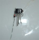
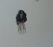
First 4 attachments show what LT says about the diode mod ( I don't 100% agree with LT - BTW). To be "action oriented" the last few attachments show a magic current mirror in the making...
last attachments are the real "magic diode" ...
I will give it a go.. enough small, subtle improvements add up.
OS
Attachments
I might try this diode thing out on my amps. Do you notice any audible difference with and without the diode ?
I'll know in 5 minutes..
OS
Hmmm, Pete, those LT differences are truly insignificant!!
When I did this a couple years back on one of my power amps, I noticed improved refinement and better image focus. Not things you can measure, unfortunately, but worth having.
Awaiting results from your 'mountain ears'!
Hugh
When I did this a couple years back on one of my power amps, I noticed improved refinement and better image focus. Not things you can measure, unfortunately, but worth having.
Awaiting results from your 'mountain ears'!
Hugh
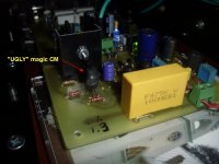
I have listened ... for hours (below - ugly CM's) .... can not note any audible changes with the diode/ CM. I did not let any non-objective statements or opinions sway my decision. Same music , 2 pairs voltage stages (w/diode - no diode BX1.3's) , same power supply/output stage and bias. NO change.
The only real changes were in the static tests , the diode forced current balance down to 1 microamp vs. no-diode 20-30uA. As seen in the LT FFT's , the distortion components were within db's and at the -100db level ... even "mountain ears" could not discern these subtle soundstage changes. Tried the headphones hooked to 220R resistors tied to the OPS ... NO change.
Tolerances of the current mirror degeneration resistors would offset the "micro" improvement of the CM current balance. And , I forgot to mention that the diode made the LTP LESS balanced in LT (slightly level shifted it). So ... thumbs down.
Edit: where this "diode trick" DOES seem to have major effects, is in a non-beta enhanced VAS where the CM/LTP sees more load (also according to LT).
OS
Attachments
Last edited:
Thanks Pete,
Much appreciated. It seems that for most purposes the diode is a waste of time. That's good; it eliminates one more component, and one less part is less time and expense to make and more reliability as well.
Cheers,
Hugh
Except for a single device VAS , is that what you did your experiment on ?
Perhaps that is the reason for different results.
The beta enhancement makes the load on the CM miniscule (see below). A 40uA/20mV - current /voltage change will swing the VAS to 110V p-p. This is with a standard KSA992/KSA1381 BE-VAS (AX/BX).
OS
Attachments
Hugh, I emailed you.
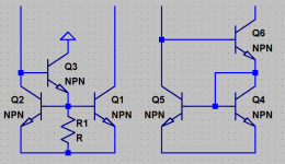
Perhaps the idea has merit, but the diode has only several uA flowing through it. Wouldn't this keep its voltage drop fairly low too? And how about trying a more capacitive, beefy diode? One could also use a third transistor, as per below. I also added a second variant for thought experiment - now the second transistor is the one with shorted C-B, the opposite extreme.
- keantoken
Attachments
After some sims...
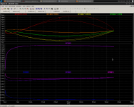
I tried to equalize Vcb for both transistors in the third example. Top graph is gain error. Bottom graphs are gain of the different mirrors.
Seemingly, Mirror 2 would give the lowest blanket THD, but Mirror 3 would give the lowest high-order harmonics. In fact, Some odd harmonics are even canceled in mirror 3. FFT last attachment.
So it appears that the performance of the CM will depend on what you put at the first transistor's collector.
- keantoken
Attachments

Last edited:
After some sims...
I tried to equalize Vcb for both transistors in the third example. Top graph is gain error. Bottom graphs are gain of the different mirrors.
Seemingly, Mirror 2 would give the lowest blanket THD, but Mirror 3 would give the lowest high-order harmonics. In fact, Some odd harmonics are even canceled in mirror 3. FFT last attachment.
So it appears that the performance of the CM will depend on what you put at the first transistor's collector.
- keantoken
Thanks for that , KT. It looks like the wilson will be in the AX1.2/BX1.4 CM, one more $.11 device will add to the other "micro-improvements". The other factor is that Nico'e ELD also successfully incorporates the wilson.
"GK" .. way back ... used the widlar enhanced CM. I tried it and did not like the results.
OS
Last edited:
Let me explain something I found about current mirrors. At low current excursions, the waveform peaks sharply because of the nonlinear diode characteristic (transconductance is low thus Dv/Dt is higher at the time input current changes direction). This peak induces pulse-like currents into the parasitics surrounding the device and can be the cause for some W_T_F moments (such as a "blip" that's always at the top of the output waveform). Interestingly, the simple two-transistor mirror is immune to this effect, unless you choose transistors with large Cbe (which should be avoided any high-performance mirror anyways).
For experiment, I tried adding degeneration to third transistor of the Wilson mirror. It still doesn't work quite as well as the diode variation. So it still stands that the harmonic profile and THD of the Wilson current mirror will depend on what you put at the first transistor's collector. In this case, a diode works better than anything else in simulation. See the attached plots for why. The orange trace is the one for the Vcb of Q6. As you can see, the diode distortion is curved the opposite direction... So apparently there is cancellation going on.
The lowest plot is the time derivative of the Vcb of Q6. This is representative of the current through any parasitic capacitor that sees this voltage. At 100KHz, full power, this can be a problem.
- keantoken
Attachments
Last edited:
I WON'T give up on the CX.
Of course , the standard diode models are very basic. Some of the MUR (ON) downloaded diode models I have behave very differently.
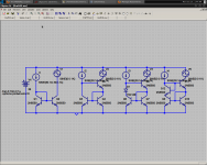
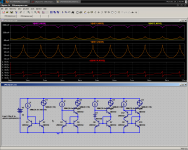
On to my recent FAILURE , I already have something better than the "goldmund killer" I just blew up (the cx) . Below is the best non-tmc'ed topology I have simulated. It is composed of a standard single ended LTP/cascode w/ current source. It THEN drives a full complimentary (leech) style differential set (like electrocompianet does) which drives a symmetrical dual differential.
WOW!! a lot of freakin' transistors. BUT , the performance matches a FULL TMC blameless and even exceeds it above 20K . over 100db loop gain and 125v slew. (below 1-3) PS , distortion is so low because BOTH even and odd are cancelled out in this one !
Stability is rock solid by either compensating the first differential or lead compensation from the VAS. I'm a gonna build it. A 100 x 100 mm VB (a little bigger).
OS
Hey, I'm finding all my silicon diode models show decreased transconductance compared to actual transistors. Is this normal?
- keantoken
Of course , the standard diode models are very basic. Some of the MUR (ON) downloaded diode models I have behave very differently.
On to my recent FAILURE , I already have something better than the "goldmund killer" I just blew up (the cx)
. Below is the best non-tmc'ed topology I have simulated. It is composed of a standard single ended LTP/cascode w/ current source. It THEN drives a full complimentary (leech) style differential set (like electrocompianet does) which drives a symmetrical dual differential.WOW!!
a lot of freakin' transistors. BUT , the performance matches a FULL TMC blameless and even exceeds it above 20K . over 100db loop gain and 125v slew. (below 1-3) PS , distortion is so low because BOTH even and odd are cancelled out in this one !Stability is rock solid by either compensating the first differential or lead compensation from the VAS. I'm a gonna build it. A 100 x 100 mm VB (a little bigger).
OS
Attachments
Last edited:
You don't understand , I stated why. single ended (first stage) cancels out even harmonics, 2nd stage (complimentary) cancels out odds. except for the vas , it is also mostly 14 cent transistors , just 4 to-126's , not much harder than a goldman/symasym. Why not ??, it's a hobby of mine .
OS
it's a hobby of mine . OS
Pete,
You are building something with Halcro performance, with almost unmeasureable distortion. Great engineering achievement, to be sure, but will it sound good? I'm betting it will be dry, surgically accurate, uninvolving. A technical tour de force, a sonic let down......
But, have a shot, see if I'm wrong. I was wrong once before, took a corner too fast in 1963, fell off my bike.....
Hugh
I was wrong once before too – but I have a mental block that prevents me from remembering just when that was.
Wait a second – I’ll pop over and ask SWMBO………(imagine the sound of my footsteps)
Oh – never mind – it seems that I’m wrong about being wrong.
I would be more specific if I could – but she’s still laughing too hard to answer!!!!
I still find it remarkable how even the high and mighty can be rapidly put into place by SWMBO. Former President Bush recently remarked that Mrs. Bush has him drying the dishes.
Heh-heh -even OS - right in the middle of designing and building some great amps - needed to take a "time out" to clean up the mess he made in the Mrs. kitchen.
Last edited:
- Status
- This old topic is closed. If you want to reopen this topic, contact a moderator using the "Report Post" button.
- Home
- Amplifiers
- Solid State
- The MONGREL (supersym II)