It has shown me why the DX/aksa55 sounds as it does and how all the others stack up.
IMHO, there is a very big difference between a DX amp and an AKSA55. Even though they are similar topology, component choice and attention to detail make a huge (hugh) difference.
")
OK , I split the grounds between the 2 banks on (attachment 1). "A" goes to the trafo CT and then to the chassis ground ? B is then separate and takes all the connections from both "G1 and G2" . Do A and B then connect separately to the chassis ? Also, is this change because of the CLC ? On the Quasi NMOS PS all amp grounds , the trafo CT , and all capacitor grounds terminate at a central star on the PS PCB.
OS
Also , would the main audio star ground be on the chassis ?
Hi ostripper,
Even though I haven't done this myself, I'd be tempted to put your on-board star earth on the output side. Allow for a connection between A and B either via a link or use quick connectors so you can experiment. I'd also allow for an off-board star earth. In short, allow it to be configurable. While you are at it, move the LEDs to the diode side and allow for a cap between AC1 and AC2. When having a takeoff point between 2 caps make sure it is from the middle of the caps.
I plan to do something very similar to prove to myself that all this actually makes a difference. I'm planning for a resistor after the diodes, so RCLC. I have a feeling it won't make much difference.
regards
Here is what national semi says about it : http://www.national.com/an/AN/AN-1849.pdfHi ostripper,
Even though I haven't done this myself, I'd be tempted to put your on-board star earth on the output side. Allow for a connection between A and B either via a link or use quick connectors so you can experiment. I'd also allow for an off-board star earth. In short, allow it to be configurable. While you are at it, move the LEDs to the diode side and allow for a cap between AC1 and AC2. When having a takeoff point between 2 caps make sure it is from the middle of the caps.
I plan to do something very similar to prove to myself that all this actually makes a difference. I'm planning for a resistor after the diodes, so RCLC. I have a feeling it won't make much difference.
regards
(also attachment below)
They seem to do it like the quasi with signal , load (speaker) and amp grounds going right to a main PCB star. the only connection to the chassis is Rg , a little 100R component. CT goes right to the capacitor bank. I think I will leave all options open and allow 2 extra fastons between A and B.
This is the PS that national uses to make for the best reference of it's LME line , so I can assume the research is already done.
OS
Attachments
Thanks, very interesting. Seems that cap works as well as a darlington.
Could you post the sim file please, going to keep it for reference, who came up with the cap idea, it seems good. I will try it in a couple of minutes on one of my 1200w x 2 class G amp which I had factory built and was delivered this afternoon and see if it works good. As long as it doesnt oscillate it should be ok. They will be doing duty tonight in a nightclub replacing two previous versions of amps I hand built 3 years ago so hopefully all goes well.

Here is the .asc file. I wonder if there would be a benefit from using 5.5V "supercaps" for the mod? Could be interesting... I replaced the BD1xx with the japanese device Bigun used on his schematic.
I found the cap trick independently, first posting it in the HAKSA headphone amp development thread. I don't know who all else knows about it, OS posted the same thing with a 100nF cap in post #314. It's a simple mod though, I don't see any use in taking credit.
- keantoken
Attachments
if you have one cap then each terminal (+ & -) is both input and output.Also , would the main audio star ground be on the chassis ?
CT to -, - to zero Volts.
Rectifier to + and + to +ve supply.
When you parallel a pair of capacitors to do the same job you could still use the input pins as the output pins, but from well arranged diagrams I have seen it can be done better.
CT to -, - to wire, wire to 2nd-, 2nd- to Zero volts
and similarly
Rectifier to +, + to wire, wire to 2nd+, 2nd+ to +ve supply.
This uses the parasitic capacitance and inductance of the wire links between the two caps as a zero cost, zero space, addition to the filtering ability of the parallel caps.
Looking at rCRC and rCLC, the parasitics of the wires can be used between all the main components.
In at one end through the parallel caps, to the R or L, in at one end of the next bank, through this 2nd bank of parallel caps to the output at the far end.
Same with the Zero Volts. EXCEPT. The Zero Volts output from the first bank has very high ripple. A short wire to a star ground located at the output of the final bank achieves the same separation effect (similar to a Power Amp and it's PSU) of big charging spikes from the low level ripples at the ground of the next stage.
Last edited:
if you have one cap then each terminal (+ & -) is both input and output.
CT to -, - to zero Volts.
Rectifier to + and + to +ve supply.
When you parallel a pair of capacitors to do the same job you could still use the input pins as the output pins, but from well arranged diagrams I have seen it can be done better.
CT to -, - to wire, wire to 2nd-, 2nd- to Zero volts
and similarly
Rectifier to +, + to wire, wire to 2nd+, 2nd+ to +ve supply.
This uses the parasitic capacitance and inductance of the wire links between the two caps as a zero cost, zero space, addition to the filtering ability of the parallel caps.
Looking at rCRC and rCLC, the parasitics of the wires can be used between all the main components.
In at one end through the parallel caps, to the R or L, in at one end of the next bank, through this 2nd bank of parallel caps to the output at the far end.
Same with the Zero Volts. EXCEPT. The Zero Volts output from the first bank has very high ripple. A short wire to a star ground located at the output of the final bank achieves the same separation effect (similar to a Power Amp and it's PSU) of big charging spikes from the low level ripples at the ground of the next stage.
Taking that advice , which "jives" with chapter 14 (D.self audio amp handbook) , I redesigned the ps100 (1st below). Knowing that the "dirtiest"
pulses are where the 1st set of reservoir caps meet the bridge rectifier , G1 from the amp boards (output transistor decoupling) is the only connect here.
G2 , which is the cap multipliers and voltage/signal board are tee'ed off the 2'nd half of the main star which is split by a wire jumper as suggested by Andrew T.
This arrangement also coincides with the national semi app note:
http://www.national.com/an/AN/AN-1849.pdf
Used the general layout rules of the app note.
It is even better with the split star , leds (so you don't die) , CLC and more robust construction. For a maximum rating , this board will do ..
Capacitor specs
100k@100v (35mm X60mm)
120k@80v
144k@63v
Amperage/wattage : with 50A bridge can handle 1 800w amp / 4R
or 2 250 -300W units. Below - are your other choices
.JUNK!!
An externally hosted image should be here but it was not working when we last tested it.
Or this , adequate for diy but crude.
Hopefully this will be the only board you will need , it will be done tonight "PS100_complete.zip"
On another note , I will add the ability to use a second regulated power supply to both powerboards for running the voltage boards. I have a 35-0-35VAC toriod but need to figure how to implement a voltage doubler to get 70v rails ... any circuits or ideas??
OS
Attachments
Hi ostripper,
Even though I haven't done this myself, I'd be tempted to put your on-board star earth on the output side. Allow for a connection between A and B either via a link or use quick connectors so you can experiment. I'd also allow for an off-board star earth. In short, allow it to be configurable. While you are at it, move the LEDs to the diode side and allow for a cap between AC1 and AC2. When having a takeoff point between 2 caps make sure it is from the middle of the caps.
I plan to do something very similar to prove to myself that all this actually makes a difference. I'm planning for a resistor after the diodes, so RCLC. I have a feeling it won't make much difference.
regards
As you see , your suggestions as well as the others are implemented. A real "mongrel" power supply.
OS
As you see , your suggestions as well as the others are implemented. A real "mongrel" power supply.
OS
I noticed
Hi OS
It looks like you've completed the revised PB60LPV1.1. This new form-factor and layout is much improved!
Taking a closer look, the fuse length of 25mm seems unusual. 5x20mm or 6x32mm (3AG) is more common.
Also, the overlay drawing implies the output inductor/resistor assembly is being done differently?
Hi OS
It looks like you've completed the revised PB60LPV1.1. This new form-factor and layout is much improved!
Taking a closer look, the fuse length of 25mm seems unusual. 5x20mm or 6x32mm (3AG) is more common.
Also, the overlay drawing implies the output inductor/resistor assembly is being done differently?
All for the people .. cheap power to the people!! Thanks for the "closer look",CSY. I added 1 -40 pixel hole to use either the 20mm or 25mm spacings, the extra trace space is there. They do make 1 " (25mm) fuses. 20 and 25mm are most common at Mouser. I use the datasheets (below-1st attachment)
to determine lead spacing and even add holes for the most common TWO components that mouser stocks in great numbers.
00300210N Littelfuse Fuseholders, Clips, & Hardware
These boards are made for what is out there..man.
I also reworked my "BABY" , the PB250 (2nd attachment). Shorter traces , ability to use second PS for voltage board/cap mult. (Vee2/Vcc2 connections).
To keep mind occupied , I make the LEECH amp (EX - 3rd attachment). Professor leach did do his homework , BUT with the modern parts and NO possibly unstable triple to deal with... I can do better. A real simple amp but needs closer match of input trannies as determined by this topology, you would just have to buy 20 each ksa992/ksc1845 and match 2 pairs for each amp.
OS
Attachments
Hi OS
Also, the overlay drawing implies the output inductor/resistor assembly is being done differently?
L1/r98 are the same just horizontal inductor (16 turns/16ga.- 20mm X 20mm=3.31034uH air core inductance. resistor goes inside.
OS
Luxman M120 - very highly regarded.
Very strange , while working on my APT1 , I came across the schematic for the Luxman M120a. Very similar to the APT(attachment 1) , but more refined. I liked the use of the FET's at the input and simulated for both the bipolar and some J201 FET's.
There are plenty of VERY good reviews of this group of amps - M-117, M-03, M-05, MX-100 ..
Luxman C120A/M120A how good? - AudioKarma.org Home Audio Stereo Discussion Forums
and many , many more..
They say it has killer bass , smooth airy soundstage. The best thing I can see is that they use the 2sa970/2sc2240, which is a dead match for my a992/ksc1845's. Upon my first simulation it worked very good , in fact , it matched the spec (attachment 2) at .013-.015% all the way from 20hz - 30khz. I tried the simulation with both 2sj201 FET's and the BJT's. With the BJT's the THD dropped to .005% even @ 30khz/200w.
I could not leave well enough alone , so I added a better CCS , 2 real compensation capacitors (2X 47pF). Another little addition:
http://peufeu.free.fr/audio/memory/memory-5-vas.html
The "magic" resistor (another one!!) This halved the 5th and 7th harmonics which correlated with the French audiophiles listening tests here:
Memory Distortion Philosophies - Part 6 : Moment of Truth
Also in (attachment 3) R6 is the adjustable CCS and R24 is the gain adjust for the level shifter. 50R for R6 gives 1.3ma per input device and 60R for R24 balances the LTP at low freq. (attachment 5). Once you do this at 100hz the input stage only get more balanced as you increase in frequency...finally getting within 3uA at 20Khz.
I like the symasym and the DX style topology but for my first voltage board to use with the PB250 , I have decided on the GX (attachment 3/4). You can't go wrong with something so simple that has the strange tendency to have rock solid THD all across the audio band and even into the ultrasonics. Mr. Holman (APT1 designer) said that he found the most linear voltage stage and THEN applied negative feedback to it. I think the Luxman beats his amp hands down even as they are essentially the same.
This amp is not PPM (who gives a poop?) , but has the strangest THD characteristics and a lovely harmonic structure (better than the symasym).
I am a little apprehensive going out on a limb like this with a new topology, but I have actually built the APT back in the "frugalamp" days.. it did not blow up or oscillate . This luxman seems to be the next logical step and it uses very similar components. The "GX1.2VB_complete.zip" will be finished tonight and actually built in september.
As far as sharing my files , I am pissed... SOME PEOPLE try to download the whole website , change their IP address after being banned , ACTUALLY port scan me to see if I get madder.. argggg. Download a few , even a hundred BUT if you get too greedy and try for the whole 40 gigabytes... You will be banned forever !!!
Just download 2/3 at a time , another 2/ 3 , do it all night for all I care , just don't DDOS me.
OS
Very strange , while working on my APT1 , I came across the schematic for the Luxman M120a. Very similar to the APT(attachment 1) , but more refined. I liked the use of the FET's at the input and simulated for both the bipolar and some J201 FET's.
There are plenty of VERY good reviews of this group of amps - M-117, M-03, M-05, MX-100 ..
Luxman C120A/M120A how good? - AudioKarma.org Home Audio Stereo Discussion Forums
and many , many more..
They say it has killer bass , smooth airy soundstage. The best thing I can see is that they use the 2sa970/2sc2240, which is a dead match for my a992/ksc1845's. Upon my first simulation it worked very good , in fact , it matched the spec (attachment 2) at .013-.015% all the way from 20hz - 30khz. I tried the simulation with both 2sj201 FET's and the BJT's. With the BJT's the THD dropped to .005% even @ 30khz/200w.
I could not leave well enough alone , so I added a better CCS , 2 real compensation capacitors (2X 47pF). Another little addition:
http://peufeu.free.fr/audio/memory/memory-5-vas.html
The "magic" resistor (another one!!) This halved the 5th and 7th harmonics which correlated with the French audiophiles listening tests here:
Memory Distortion Philosophies - Part 6 : Moment of Truth
Also in (attachment 3) R6 is the adjustable CCS and R24 is the gain adjust for the level shifter. 50R for R6 gives 1.3ma per input device and 60R for R24 balances the LTP at low freq. (attachment 5). Once you do this at 100hz the input stage only get more balanced as you increase in frequency...finally getting within 3uA at 20Khz.
I like the symasym and the DX style topology but for my first voltage board to use with the PB250 , I have decided on the GX (attachment 3/4). You can't go wrong with something so simple that has the strange tendency to have rock solid THD all across the audio band and even into the ultrasonics. Mr. Holman (APT1 designer) said that he found the most linear voltage stage and THEN applied negative feedback to it. I think the Luxman beats his amp hands down even as they are essentially the same.
This amp is not PPM (who gives a poop?
) , but has the strangest THD characteristics and a lovely harmonic structure (better than the symasym).I am a little apprehensive going out on a limb like this with a new topology, but I have actually built the APT back in the "frugalamp" days.. it did not blow up or oscillate
. This luxman seems to be the next logical step and it uses very similar components. The "GX1.2VB_complete.zip" will be finished tonight and actually built in september. As far as sharing my files , I am pissed... SOME PEOPLE
try to download the whole website , change their IP address after being banned , ACTUALLY port scan me to see if I get madder.. argggg. Download a few , even a hundred BUT if you get too greedy and try for the whole 40 gigabytes... You will be banned forever !!!Just download 2/3 at a time , another 2/ 3 , do it all night for all I care , just don't DDOS me.
OS
Attachments
There is a low output heavily biased one that I have heard good words about by a mate. LUXMAN | PRODUCTS | INTEGRATED AMPLIFIER L-590AII
Any special info on that one BTW?
Any special info on that one BTW?
OS, be bold. Nothing wrong with going out on a limb... There was apprehension about my headphone amp but it's stable and playing beautifully into my 8inchers! It has not blown up despite being abused with 4 ohm speakers.
I was nearly sure the funky compensation would not work... But it does. Try getting 46db OLG at 100KHz! (on that note, look at C104a and R111a, and notice Cdoms are only 5pF... This is very much like what I use in my headphone amp and have simulated on power amps before)
With the bold approach however, you've got to go the whole hog. Be thorough. If there's a way to make it work, be sure to find it. It may be demanding, but so are most things worthwhile in life.
The main reason it's discouraged I think is that if you screw up, there aren't many around that can help you, few people go down the rabbit hole. That's not really a problem on DIYAudio, right?
I was going through your pictures, OS. I think I went through several hundred files, just looking at thumbnails on the HTML's. I noticed someone downloaded your entire PDF folder. Sheesh! At least make an appointment!
- keantoken
There is a low output heavily biased one that I have heard good words about by a mate. LUXMAN | PRODUCTS | INTEGRATED AMPLIFIER L-590AII
Any special info on that one BTW?
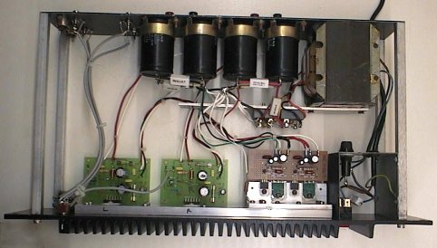
Salas , the L-590A looks just like the L507u (attachment) the power supply , amp boards everything. I have the schema for the 505u and it is a 100w class AB with the same topology as the M120a. It seems Luxman stuck with what worked ... and sounded good.
Since the amps boards look EXACTLY the same , I wouldn't be surprised if luxman just use the same board with lateral mosfets and Bias them into class A. I did this in my simulation with IRFP240/9240's outputs and matched that .03/.005% spec exactly.
I am going to have 2 X the new luxman 509u in my PB250/GX combo powered by my 1KVA+ 30lb. toriod. So for 1/20 the price of the real thing I get twice the OHMMPH!!
Hey , keen... this is why I am going modular. I can unscrew 6 euroblock terminals, bring the voltage amp to the bench , hook it temporarily to a PB60 test jig with junk heatsink ... scope it , probe it ,alter it if needed. 7-15$ per voltage board... can't be beat!!
As far as downloading whole PDF collections , I set limits and even banned a whole range of IP adresses (they came from asia).
OS
Attachments
Last edited:
Cheers. Your hunch they just tweaked the output to a new class A model seems very plausible. I think I remember they used to have bias button A/AB in some of their heavyweights in the 80's.
P.S. I drooled over that one as a teenager http://www.thevintageknob.org/luxman-L-550.html
P.S. I drooled over that one as a teenager http://www.thevintageknob.org/luxman-L-550.html
I was nearly sure the funky compensation would not work... But it does. Try getting 46db OLG at 100KHz! (on that note, look at C104a and R111a, and notice Cdoms are only 5pF... This is very much like what I use in my headphone amp and have simulated on power amps before)
I was going through your pictures, OS. I think I went through several hundred files, just looking at thumbnails on the HTML's. I noticed someone downloaded your entire PDF folder. Sheesh! At least make an appointment!
- keantoken
I got 36 db at 100k with 5pF. This is the only simulation I can go that low with except for Roenders RMI folded cascode amp.
The main reason it's discouraged I think is that if you screw up, there aren't many around that can help you, few people go down the rabbit hole. That's not really a problem on DIYAudio, right?
Most just build a DX ,self amp or something generic. Been there .. done that, I want audiophile DIY. This is a sure bet. I am amazed how the sim matched the manufacturers spec perfectly. I also simulated with the A970/c2240 models , same results.
OS
Attachments
Cheers. Your hunch they just tweaked the output to a new class A model seems very plausible. I think I remember they used to have bias button A/AB in some of their heavyweights in the 80's.
P.S. I drooled over that one as a teenager Luxman L-550 on thevintageknob.org
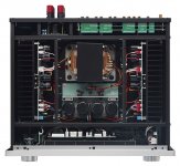
That is one strange amp (below) , wonder what happens when the heatpipes wear out ? They do have a lifespan , similar to the new processor (cpu) heatpipe versions versions. I opt for very large convective cooling.
I have a MUCH larger power supply than those amps ... so I might just exceed the "drooled over" amp. I never gave 2 thoughts to class A after having the room heater Genesis stealth .. as I have said before , a symasym sounds just as good (I A/B'ed them -same loudspeakers) and does not make you SWEAT!!
OS
Attachments
I never gave 2 thoughts to class A after having the room heater Genesis stealth .. as I have said before , a symasym sounds just as good (I A/B'ed them -same loudspeakers) and does not make you SWEAT!!
OS
Did you ever listen to Pass X line? Or had one from the F DIY line by any chance? Those are interesting examples of the hot persuasion to lend an ear.
Attachments
- Status
- This old topic is closed. If you want to reopen this topic, contact a moderator using the "Report Post" button.
- Home
- Amplifiers
- Solid State
- The MONGREL (supersym II)