by Dr. EM - I certainly don't mind a more complex design if the parts go toward creating better performance
The design is only slightly more complex than my present one. The 2 transistor CCS's can be SMD dual devices (2n5550) or .08 cent ksc/a 1845/992 devices. The only important design criteria parts- wise is the KSC3503/KSA1381 VAS.
I will begin now to Tidy up the schema , use the new LT to generate a BOM , and make my boards.
And thank you , KEAN. When I finish , I might give you the boards in post #8 !
OS
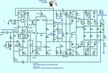
Finalized the Schematic and generated a BOM .. very verbose. Board layout is next.
A mongrel ..
ThanX again, Keen.. ,your simulations are the teeth that bite..
OS
A mongrel ..
An externally hosted image should be here but it was not working when we last tested it.
ThanX again, Keen..
,your simulations are the teeth that bite.. OS
Attachments
When I finish , I might give you the boards in post #8 !
OS
That would be great!
Look at these two OLG plots. They are of the same Mongrel, but with different plot settings. The one on the left has "unravel branch wrap" clicked. The one on the right is without. So your OLG phase actually comes around a full 360 degrees and lands at 101 in the right place. Interesting. I was simulating with the first graph, which explains why my compensation is always rather extreme... AARGH.
- keantoken
Attachments
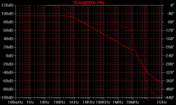
The thing that's confusing is why the circuit is so stable in transient analysis while the OLG phase margin is way out there.
Way out there ? Below (attachment 1)is typical of most amps on the forum (I have simulated them all).
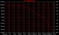
here is a generalized bode plot of loop response ...

Another one..
An externally hosted image should be here but it was not working when we last tested it.
90db below the "breakpoint" coincides with unity gain.
Here is a thread you should read.. http://www.diyaudio.com/forums/solid-state/133306-frugalamp-os-13.html ... Post 128 starts the lesson. post 139 and 145 concludes the lesson. Cdom , the LTP degen. resistance and any lead comp. will affect the final Bode plot.
BTW - the bode plot below shows a bit of overcompensation.
OS
Attachments
Have you simulated a +/- 30V version of your amplifier that uses lower noise, higher hfe transistors?
I'm a believer in the Thermal Trak output transistors with packaged thermal sense diodes, especially for class B amps. Have you tried them in your amps?
An amp specifically designed for 30V- 35V could have advantages over an amp designed for 75V but run down at 30V. It might be very popular and easier to obtain parts.
Common low cost, low noise, high hfe transistors
BC550C BC560C 45 volt
BC549 BC559C 30V
BC556B BC546B 65V for cascodes
Lower capacitnce Thermal Trak 180 watts
NJL0281D NJL0302d
linesource - lower noise, higher hfe transistors
What transistors are they ?? ks-a992/c1845 have 400-800 Hfe (grade E), Cob 2pF - very low noise (uA) , the only Xters I've seen higher are some of the Zetex line. ( Ztx1056- Hfe1200 http://www.diodes.com/zetex/_pdfs/3.0/pdf/ZTX1056A.pdf )
I'm a believer in the Thermal Trak output transistors with packaged thermal sense diodes, especially for class B amps. Have you tried them in your amps?
Too expensive , too hard to source. They are a fad , they will be gone soon.
An amp specifically designed for 30V- 35V could have advantages over an amp designed for 75V but run down at 30V. It might be very popular and easier to obtain parts.
This amp will run great at +-50 V rails. Most recycled audio equipment have 300-400 VA 40-0-40 trafo's. What is wrong with a little extra headroom (300w peaks) , I am a firm believer in that.
OS
Member
Joined 2009
Paid Member
By bigun - Do I understand right - the outputs don't switch off ? And this thing sounds as good as a pure Class A amp ? - then this is great !
Let me clarify , this op stage exhibits non-switching tenancies to a much higher power level than a standard class B type 2 EF. All class B stages work in class A at low power levels , this one carries the effect to a higher level even without the feedback to the CCS's.
One note , this was done in simulation.
At 1/2 power the amp goes true B with full switchoff , but still with reduced Xover distortion (especially H5,7,9,11). With Keen's super low noise floor these higher order components are 125 - 140 db down! GONE
I have used both the standard models from ON and Andy c.'s special ones , SAME RESULTS. All the other amp OPS's (EF2 ,triples) ,do not exhibit this behavior.BTW , the krill's non- switching behavior also degrades with level/load. IF you want FULL non-switching get a couple of LT1166's (IC below) link: http://cds.linear.com/docs/Datasheet/lt1166.pdf
I might add this as an add-on to this amp , VERY easy to implement.
OS
Attachments
Linesource has a point, there is a cascode so other LTP trannies can be used, mpsa18 for instance has lower noise and higher hfe. In 99 percent instances the max hfe figures given in datasheets are never reached so you will be lucky finding 992/1845 at 600, while its common finding mpsa18 at 800, lucky when you finding them at 1000. There are offcourse many other transistors having high hfe, some even reach 10 000, darlingtons. For these type applications I use a tranny having common hfe around 1000 and cob is only 1.8pf (not that it matters that much when its cascoded), only slightly higher than 1845, noise figures will be much better too. I think those BC parts will have better noise figures than the fairchilds in general, but because noise figures is a complex subject Id rather not get into it here but for optimizing a circuit for noise youll see the benefits of having high beta parts around although this is not the only important parameter.
Os for us to be able to compare we need more detailed parameters than say, half power, give us a frequency too. Use say 20 volt swing at 20KHZ plz, I would just like to make a interesting comparison with a amp of mine. My amp displays lower THD than yours Im pretty sure using quite a few less active parts but what Im interested in is to see how the distortion figures compare but the ones of most interest is the ones from 7th onwards. The idea is to see how much the frontend influences these higher harmonics ie Im gonna be surprised if my amp displays lower distortion figures for 7th and up, although not for the THD. In my amp I just use a common triple in class ab biased at 60 ma. I cannot have so much complexity in a amp used in cars, so I rather design around very fast, very linear circuits, optimize the operating current of each active part and parts selection to get high performance.
Os for us to be able to compare we need more detailed parameters than say, half power, give us a frequency too. Use say 20 volt swing at 20KHZ plz, I would just like to make a interesting comparison with a amp of mine. My amp displays lower THD than yours Im pretty sure using quite a few less active parts but what Im interested in is to see how the distortion figures compare but the ones of most interest is the ones from 7th onwards. The idea is to see how much the frontend influences these higher harmonics ie Im gonna be surprised if my amp displays lower distortion figures for 7th and up, although not for the THD. In my amp I just use a common triple in class ab biased at 60 ma. I cannot have so much complexity in a amp used in cars, so I rather design around very fast, very linear circuits, optimize the operating current of each active part and parts selection to get high performance.
Use say 20 volt swing at 20KHZ plz
Do you mean 20V p/p or +-20 (40V p/p) ???
Here is all the 20k output...
Simulation is included last.
OS
Attachments
Member
Joined 2009
Paid Member
The MPSA18 has higher gain
how does it have gain ? it only exhibits gain when it's in a circuit and the gain is determined by the components around it ?
hfe - is not gain, it's the input impedance of the base, and it's not constant.
Member
Joined 2009
Paid Member
Higher voltage gain no, current gain yes. Hfe is known as static current gain.
- keantoken
I'm just causing trouble for the sake of it aren't I ? - but my newbie way of keeping things simple is to treat BJTs as voltage controlled devices and hfe just doesn't fit into that narrow way of seeing things. I think hfe is misleading, it's a curve (not a straight line) on a graph that gets interpreted as a 'current gain' and I prefer to see it instead like this: a BJT is a voltage controlled device, the voltage is between base and emitter. To maintain this voltage you need a voltage source that can provide current into the base. This is really another way of saying you have an input impedance. It is a non-linear function of several variables. If you draw a graph of base current against emitter current you get a curve - if you squint at the curve you can draw a straight line somewhere and call the gradient a 'gain' and then you get to complain that the behaviour goes non-linear when you move away from the part of the curve you tried to fit a line against. Yuck.
By homemodder- pretty sure using quite a few less active parts
TOO MANY PARTS
!I am using
An externally hosted image should be here but it was not working when we last tested it.
http://www.diodes.com/datasheets/ds30304.pdf
Whole input pair/cascode/2 CCS's will take up less room than the input cap , no stupid matching ,either.
OS
Thanks Os thats perfect, It still seems to me that getting absolute low thd figures is the way to go. Ill show some plots and the output stage which is common but the input and vas I will cover sorry. I wont bother showing 1K plot figures they are just too small but i can include a 50khz or 100 khz plot to show what the circuit is capable of.
Kean, Id say yes and no, depends where the part is used, in Os circuit the ltp transistors are cascoded, so theres no cob problem. Now think about early voltage and what effect the higher hfe is going to have on various parameters,(common mode distortion, noise, dc offset, PSRR) and it will become clear why the mpsa18 will outperform the 1845, not to mention that its noise figure is lower too.
Kean, Id say yes and no, depends where the part is used, in Os circuit the ltp transistors are cascoded, so theres no cob problem. Now think about early voltage and what effect the higher hfe is going to have on various parameters,(common mode distortion, noise, dc offset, PSRR) and it will become clear why the mpsa18 will outperform the 1845, not to mention that its noise figure is lower too.
- Status
- This old topic is closed. If you want to reopen this topic, contact a moderator using the "Report Post" button.
- Home
- Amplifiers
- Solid State
- The MONGREL (supersym II)