Cool....
Strip it down , post some pictures .. let's see how kenwood does it !
Once you do that , it should be easy to retrofit it with DIYamps.
You have, (hopefully)-
1. A nice looking case.
2. A good 40-0-40V+ 500VA trafo (estimate).
3.sufficient thermal solution (HS) to dissipate 300W.
4.input/output hardware (jacks/terminals) , not too much drilling.
You would want to ditch the main power supply caps , they are most likely at the end of their life. Cheap phenolic boards , bye-bye (after you have them photographed).
In the end , you could most likely make a 120-150w DIY amp out of it for 50-75$ TOTAL. NO "hackjob" , make the PCB's to fit the unit, output trannies to use the original holes , etc.
PS - Ebay or street unit ???
OS
If you'd like the circuit board, I can mail it to you. It could be used as a subwoofer amplifier as it has rich bari and bass, but the high fidelity ends there. Output devices are big Sanken, but they're not parallel. It was reliant on a relay and a custom circuit to prevent DC offset during power down.
1). Ah, well the case can be spruced up, such as with my own personal curse of having to take my own advice very soon after I give it--this time, its the exercise with the black sandpaper for turning the black aluminum to silver and Rustoleum Clear Lacquer to finish it out. lol! Does anyone else hate the black box look?
2). Okay, going to run measure. . .
VAC: 54.8, 0, 54.8
About 6 ampers capacity
The transformer fills about 1/3rd of the enclosure.
There's a bonus rail of 27.7vac, which might be fun with rail splitter and regs to run a fet buffer, or maybe the Moosefet with IRF510 on a tape loop like switch (for those sources that need a boost).
3). It won't dissipate 300w safely, but it might could run a rather efficient 150w per channel, 2 channel amplifier (with the hopes of most of that energy ending up in the speakers, not the heatsink). There's two heatsinks of 2" x 3.5" x 7.5" That looks questionable if 4 ohm speakers. Fortunately, the heatsinks are also bolted several times to the well ventilated metal enclosure.
4). Input and output terminals? Ah, Kenwood used the cheapest. I'd like to upgrade it to decent insulated RCA jacks for input and Oversize spring clip for speakers (clumsy-proof, and strong nonstop contact pressure). There's plenty of these enclosure parts here already.
As for power caps, I'd like to use whatever new caps come with the AX kit. Hopefully that's available. A limp alternative would be exact stock numbers for various on-line stores.
Hackjob? Yes please. Its gotta be do-able! These parts in the Kenwood will most certainly be gathering dust until a rather complete kit arrives to use them. The miserable alternative is far too expensive and terrible complex shopping that turns out to be futile. . . for people who are unaccustomed to shopping for discrete parts.
Ebay or street unit? lol!
") Street unit? I traded a laptop hard drive for it. The very sturdy transformer and the decent heatsinks seemed to be a good deal, but that was merely a guess.
Street unit? I traded a laptop hard drive for it. The very sturdy transformer and the decent heatsinks seemed to be a good deal, but that was merely a guess.
Last edited:
54.8Vac open circuit is going to need 80V or 100V capacitors.Vac: 54.8, 0, 54.8
About 6 amperes capacity .....................
3). It won't dissipate 300w safely, but it might could run a rather efficient 150w per channel, 2 channel amplifier (with the hopes of most of that energy ending up in the speakers, not the heatsink). There's two heatsinks of 2" x 3.5" x 7.5" That looks questionable if 4 ohm speakers..
Under quiescent load it will provide ~ +-73Vdc.
That is good for at least 200W+200W into 8r+8r (requires output of 56.6Vpk), but more likely 250W into 8r0 (63.2Vpk)
ClassAB for domestic use, outputs an average of ~1% of maximum power (2W) leaving room for +20dB transients.
Using high Re values of say 0r5 on a 3pair output stage (a total of 12 mj21193/4 for stereo) would require Ib=50mA/pr giving Pq=22W for each channel. Those sinks will run warm for domestic use.
I would not even think about 4ohm nor 6ohm speaker with that PSU voltage.
Pushing Re to 1r0 would reduce the Pq ~11W to 12W/ch
What is the point of guessing when it can be modeled?
Last edited:
Do you have a camera , daniel ?? take photo's , I can reverse engineer remotely.
I could not find a inside shot for that kenwood. I do this for all the ebay amps I buy (before I buy).
This is a OEM amp , not a overbuilt DIY one. They will pair up 1/2 pair mt-200 sankens up with a PS that will "sag" before the sankens SOA is exceeded. The NIKKO had 2 pair MT-200 sankens driving 4R PA speakers at block parties for 19 years before it failed.
They "underdesign" the PS to match the SOA of the output devices , if Daniel stays in the same ballpark with total capacitance and the equivalant OPS , it should hold together for another 15 years. My nikko mod is only 10% over in SOA/ capacitance versus the original. Bet the kenwood is 2 X 15kuf @80V
TAKE PHOTO'S dan , I would even make boards custom to your layout.
OS
I could not find a inside shot for that kenwood. I do this for all the ebay amps I buy (before I buy).
By Andrew T. - 54.8Vac open circuit is going to need 80V or 100V capacitors.
Under quiescent load it will provide ~ +-73Vdc.
That is good for at least 200W+200W into 8r+8r (requires output of 56.6Vpk), but more likely 250W into 8r0 (63.2Vpk)
This is a OEM amp , not a overbuilt DIY one. They will pair up 1/2 pair mt-200 sankens up with a PS that will "sag" before the sankens SOA is exceeded. The NIKKO had 2 pair MT-200 sankens driving 4R PA speakers at block parties for 19 years before it failed.
They "underdesign" the PS to match the SOA of the output devices , if Daniel stays in the same ballpark with total capacitance and the equivalant OPS , it should hold together for another 15 years. My nikko mod is only 10% over in SOA/ capacitance versus the original. Bet the kenwood is 2 X 15kuf @80V
TAKE PHOTO'S dan , I would even make boards custom to your layout.
OS
2). Okay, going to run measure. . .
VAC: 54.8, 0, 54.8
About 6 ampers capacity
The transformer fills about 1/3rd of the enclosure.
using Daniel's measurements and his guesstimate of current capacity he has ~625VA transformer. That is hardly within the definition of "OEM undersized" for a 200W+200W into 8r+8r amplifier and 240 to 250W is still possible with one channel driven.This is a OEM amp ,.......................
They "underdesign" the PS to match the SOA of the output devices ,
If it's only 4Aac (~400VA) then he should still get 200W into 8r0 with one channel driven and at least 180+180W into 8r+8r from a sagged PSU (53.7Vpk + 6V losses + 13V sag = 73Vquiescent).
We need pics... By the weight , (8.8KG) you are most likely correct and it does have a large trafo 500KVa+ (monster EI - I saw a picture) and possibly 3 pair MT-200/per channel. A bit bigger than my nikko. The KM 893 is the 120W version at 6.8KG. A very hard to find schema.
Regardless , a "kit" won't fit .. make a custom power board/ax-ex module setup , reuse the heatsinks and trafo.
OS
Regardless , a "kit" won't fit .. make a custom power board/ax-ex module setup , reuse the heatsinks and trafo.
OS
AndrewT is correct on the rails voltage. Its 73.75, measured from the output devices. Curiously, the cable from the only circuit board to the transformer is about 10" of remarkably thin ribbon cable. There's an ordinary square rectifier unit and a pair of 10,000uF caps. The amplifier runs warm at idle but doesn't appear to dissipate much more while driving speakers.
I'm sorry that the digital camera is lost. Its a newer model and its in a little camouflage case about the size of a deck of cards. This looks like a little rock. We just can't find it. I can try with the webcam that's on the MSI Wind, maybe this evening, sometime after much driving around in circles with the brush hog and tractor.
I'm sorry that the digital camera is lost. Its a newer model and its in a little camouflage case about the size of a deck of cards. This looks like a little rock. We just can't find it. I can try with the webcam that's on the MSI Wind, maybe this evening, sometime after much driving around in circles with the brush hog and tractor.
brush hog and tractor ??
Farming ??
I start the peppers and tomato's now inside and the salad stuff outside ... yummy.OS
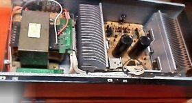
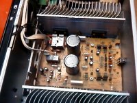
Here's photos of the inside of the Kenwood.
Maximum possible size of the amplifier board is: 6-1/16th x 7-1/4 inches
However, a slightly smaller size would be easier to install.
Maximum possible size of the amplifier board is: 6-1/16th x 7-1/4 inches
However, a slightly smaller size would be easier to install.
Attachments
Last edited:
My earlier estimate of amperage may have been overly optimistic by the entire difference of what it could do versus what it should do, and that's really different.
What it "should" do is plausibly 475va.
Would it be correct to assume that voltage regulation seems to be a concern?
What it "should" do is plausibly 475va.
Would it be correct to assume that voltage regulation seems to be a concern?
The kits would fit , you just have flat one-sided "skived" heatsinks ... drill 7 holes - done. IF they the full 5" tall you could even go for flat mounting and make a PS50 or similar for the middle. Ha. ha... just one pair MT-200 outputs for 73v rails ... andrew T. would shoot the designer !!
PS - unless it works and you just want to recap it ??
OS
PS - unless it works and you just want to recap it ??
OS
The lack of smoothing capacitance must be helping to save from disaster.
They could have a bit of deliberate resistance built into the wiring from Secondary to Amp PCBs.
Yes, I was suggesting 1500W of BJT for the output stage (3pair of MJ21193/4) whereas it looks like 400W of output devices have been used to save money.
The protection locus must be very robust to make the devices survive ham fisted operators.
The kits would fit , you just have flat one-sided "skived" heatsinks ... drill 7 holes - done. IF they the full 5" tall you could even go for flat mounting and make a PS50 or similar for the middle. Ha. ha... just one pair MT-200 outputs for 73v rails ... andrew T. would shoot the designer !!
PS - unless it works and you just want to recap it ??
OS
Its outputs are 2SA1494, 2SA3858
Well, we might could assume that replacing caps won't fix Kenwood's design; so, I would like to consider addressing the actual problem by removing their amplifier board.
Do you think that the transformer, enclosure and heat sinks are usable for the AX kit?
Yes , andrew .. small gauge wiring. Those MT-200's http://www.sanken-ele.co.jp/en/prod/semicon/pdf/2sa1295e.pdf are 200W/17A devices (400w of dissipation) .
....The biggest sanken audio devices. My nikko had 2 pair smaller sankens
http://www.sanken-ele.co.jp/en/prod/semicon/pdf/2sa1215e.pdf as output. Does this not smell of deception ? Nikko = 120W / Kenwood= 150w ???
2 pair of my NJW's are over 600w (15A / 150w) , a perfect match for the nikko and a real upgrade for the poor "under- engineered " kenwood.
I have 6 extra of those...
OS
....The biggest sanken audio devices. My nikko had 2 pair smaller sankens
http://www.sanken-ele.co.jp/en/prod/semicon/pdf/2sa1215e.pdf as output. Does this not smell of deception ? Nikko = 120W / Kenwood= 150w ???
2 pair of my NJW's are over 600w (15A / 150w) , a perfect match for the nikko and a real upgrade for the poor "under- engineered " kenwood.
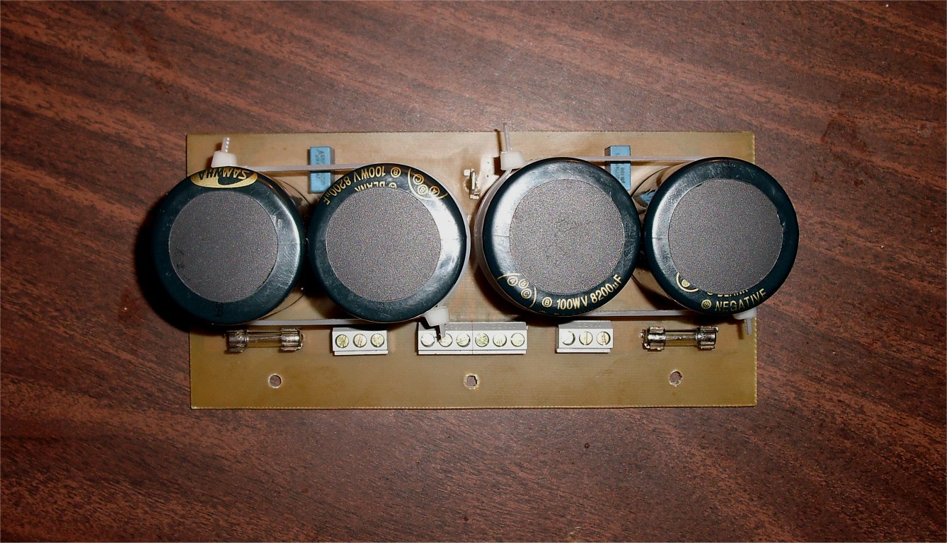
They were made for it !!! As long as the heatsinks are 100mm (4") tall. Flat mount , put a 4 X 8200uF @ 100v PS in between.Do you think that the transformer, enclosure and heat sinks are usable for the AX kit?
I have 6 extra of those...
OS
Last edited:
Sounds rather like my Teac, it had 70V supplies and yet only one pair of Toshiba 2SC2565/2SA1095. The main board in the middle of the heatsinks is only 125mm wide and 240mm long, containing only the main supply capacitors, drivers, and outputs (and the protection circuit). The voltage gain circuitry was on a seperate pcb and connected by wire. Not surprisingly there were compensation capacitors all over the place.
The heatsinks are about 240mm wide, 70mm tall with a 5mm thick backplate, and 50mm fins. It is a proper extrusion though. Not black anodised.
I think the original A919DC was specced at 100W per channel into 8 ohms, which made me wonder why on earth they used 70V supplies!
The heatsinks are about 240mm wide, 70mm tall with a 5mm thick backplate, and 50mm fins. It is a proper extrusion though. Not black anodised.
I think the original A919DC was specced at 100W per channel into 8 ohms, which made me wonder why on earth they used 70V supplies!
But the component is 5 " tall (I have the manual) .. are the heatsinks raised off the bottom or do they not touch the top ?
OS
The heat sinks are 3/4 inch away from the top. The rear panel is 4-5/8" tall, so the manual's height dimension seems to have included plastic feet.
Then they will fit , facing down with the 7 devices bolted upside down along the bottom. The input edge of the board will be at the top. you will be left with 1/4 " at the top.
My reason for concern , I just may give you 2 PCB's (you be the guinea pig)
PS - you still could just recap the original
OS
My reason for concern , I just may give you 2 PCB's
(you be the guinea pig)PS - you still could just recap the original
OS
I did have a thought - how about designing a board where the drivers/output is on the main board, and then put all the small signal stage stuff on a little module that you could mount at 90 degrees to the main board? It's a trick often used in ATX power supplies to get more space.
- Status
- This old topic is closed. If you want to reopen this topic, contact a moderator using the "Report Post" button.
- Home
- Amplifiers
- Solid State
- The MONGREL (supersym II)