Os I see you are playing around with circuit resembling the pioneer m90, we talked about it a bit in that very old thread of yours, do have sim files of it like the other amps, I hope you build it, its a interesting design and its not easy to get perfectly stable but then again I didnt try with just EF but only triples which could have made the problem worse.
Os I see you are playing around with circuit resembling the pioneer m90, we talked about it a bit in that very old thread of yours, do have sim files of it like the other amps, I hope you build it, its a interesting design and its not easy to get perfectly stable but then again I didnt try with just EF but only triples which could have made the problem worse.
You mean the PX .. it gave phenomenal THD and slew. with an EF2 ,it was stable with compensation just at the input pair. This topology does not work with conventional miller/VAS compensation.

below is the LT file with all it's PPM goodness...
OS
Attachments
I simmed it last year and built a prototype on vero board, sounded pretty good but I had some oscilation problem, probably due to the prototype and the triple, without careful layout a triple is bothersome. Looking forward to see a proper pcb board so I can try it properly, the member and designer Apex says its the best amp he has ever heard. I dont have enough time to design and to test so many different designs.
Designers here are very much against the three stage voltage amp route, they are harder to compensate but I like the wide bandwith. BTW electrocompaniet which Im a big fan of and proud owner of a intergrated amp and two monoblocks has recently won 3 absolute sound golden ear awards of which, one for the AW250R amp. This is the intergrate I have except mine is a older model but the design is virtually the same and uses 3 stage voltage amp.
Designers here are very much against the three stage voltage amp route, they are harder to compensate but I like the wide bandwith. BTW electrocompaniet which Im a big fan of and proud owner of a intergrated amp and two monoblocks has recently won 3 absolute sound golden ear awards of which, one for the AW250R amp. This is the intergrate I have except mine is a older model but the design is virtually the same and uses 3 stage voltage amp.
Hi Os,
Your enthusiasm and energy is amazing. Thank you very much for this thread.
I am very much interested in building the Luxman version GX even though I have 3 unfinished projects to complete. As I am not technical can you please assist with the questions below?
1. Are the KSA1220A/ KSC269A transistors preferred over the KSA1381/ KSC3503 for Q9 and Q12?
2. For R12 in the LTP the diagram calls for a 500ohm trimmer the BOM says 200ohms. Which is recommended?
3. Can I increase the value of the filter caps C89 and C93 before the voltage regulators? Will I get a thump on turn off if increased?
4. As I will drive <4 ohm speakers can I use 5 pairs of the NJW21193/4 transistors on the output ie will the drivers MJE15032/33 cope? I know 4 pair are within the SOA for 70Vdc but I would like to experiment with higher bias like the new Luxman amps.
Thanks
Harry
Hi Os,
Your enthusiasm and energy is amazing. Thank you very much for this thread.
I am very much interested in building the Luxman version GX even though I have 3 unfinished projects to complete. As I am not technical can you please assist with the questions below?
1. Are the KSA1220A/ KSC269A transistors preferred over the KSA1381/ KSC3503 for Q9 and Q12?
2. For R12 in the LTP the diagram calls for a 500ohm trimmer the BOM says 200ohms. Which is recommended?
3. Can I increase the value of the filter caps C89 and C93 before the voltage regulators? Will I get a thump on turn off if increased?
4. As I will drive <4 ohm speakers can I use 5 pairs of the NJW21193/4 transistors on the output ie will the drivers MJE15032/33 cope? I know 4 pair are within the SOA for 70Vdc but I would like to experiment with higher bias like the new Luxman amps.
Thanks
Harry
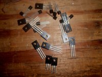
The KSA/C 1220 and 2690's are better. Since they are cascoded by the hawksford , their superior speed will improve performance. The 1381/3503 pair still work well. If you can hold on a few days a more concise , professional package will be submitted. I am now armed with the better tools (see PCB's below).
For a higher bias and the MJW21193/4 , you might want to use FJP1943/5200 "o"grade , these bad boys are the "beefiest" TO-220's out there with 120+ Hfe and over 1A SOA@70V.
NEW STUFF COMING SOON... ALL THE MONGRELS... (AX ,BX ,CXbjt/fet ,EX,GX).... REDESIGNED.
OS
Attachments
I hope people is beeing kind with him.
I will be with him if someone or something interrupt the peace and harmony here.
regards,
Carlos
Thank you, Sir Carlos. I do appreciate your Blame ES , as I have heard it sound as good as the luxman (GX) or even better than symasym (the old CX). While being far simpler.
The new CX might match them all with a little compensation "magic". I am still evaluating the "CXbjt" (3rd board above). VERY impressive.
OS
NEW STUFF COMING SOON... ALL THE MONGRELS... (AX ,BX ,CXbjt/fet ,EX,GX).... REDESIGNED.
OS
Looking good Pete! I like it that you have still provided generously sized solder pads (and track widths)---some of the pads from group buys on this site are soooooooo small it makes assembly difficult.
Steve.
Hi OS,
Have just finished assembling my boards and now need to start setting all of the trimmers.
Post # 651 suggests that CCS should be set to 100r and LS to 40r which I have done, is this still correct with 40v rails? Do I measure the offset when setting R12 at the PD+ and ND- points?
I'm also not sure what to do with the vbias adj on the PB120 board.
I'm sure these are all basic questions, just being cautious before I power it all up.
Much thanks,
Pete.
Hi OS,
Have just finished assembling my boards and now need to start setting all of the trimmers.
Post # 651 suggests that CCS should be set to 100r and LS to 40r which I have done, is this still correct with 40v rails? Do I measure the offset when setting R12 at the PD+ and ND- points?
I'm also not sure what to do with the vbias adj on the PB120 board.
I'm sure these are all basic questions, just being cautious before I power it all up.
Much thanks,
Pete.
The vbias adj should initially be set at max resistance. A sure fire way to ABSOLUTELY avoid any damage is to omit the final outputs and tack 2 -33R 1/2w resistors from the emitters of the mje15032/33 drivers to the NFB point.
.
At this point you should have 300- 400 mv between PD+ or ND- and ground. Both readings should be close (within 20-30mv). Mine read +.430 / -.443V , for example.
..remove the 33R's before adding the main outputs !
After putting the outputs in , they should be way underbiased ... adjust Vbias until you get 11- 14 mV across your .22R emitter resistors. This will also read as about 1.27V between PD+ and ND- .... DONE!!
Recheck after operation (warm up) adjust for a warm (not hot) heatsink.
OS
Last edited:
My CX "U" (goldmund killer) is DONE !
I have MY answer to all the fluster and fussin' on the 2 crazy goldmund threads. NO groupbuys , no B__S , just good old country cookin'.
The PCB package is for just the voltage board , it can be used with all the current power boards (PB60/120/250). It can be used with MPSA18 OR LSK170/389 input pairs and will accept conventional miller compensation OR transitional miller comp.
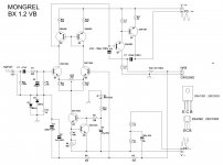
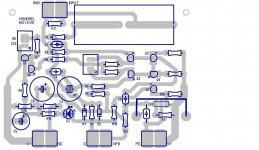
I will make a MOSFET board to go with it this coming weekend for you goldmund fans. This amp sounds GREAT !! , is very stable and economical to make. The package includes the sprint layout (gerbers , drilling) , a JPG for the toner people, and overview/schematic , and a sprint generated BOM. BX is totally done as well (with TMC option) all in the "mongrel" site or attached ( it fits). On these, I mean business .. top quality..(thanx Alex MM)
The BX voltage board is being enjoyed WITH TMC right now !! Awesome. With some of the lowest simulated THD and the BEST FFT , the BX is almost to good to be true for such a simple DIY creation. Carlos and friends surely must be in heaven with this topology. The CX is comparable .. but with 3X the parts. (below FFT for CX and BX - last 2 plots)
OS
I have MY answer to all the fluster and fussin' on the 2 crazy goldmund threads. NO groupbuys , no B__S , just good old country cookin'
. The PCB package is for just the voltage board , it can be used with all the current power boards (PB60/120/250). It can be used with MPSA18 OR LSK170/389 input pairs and will accept conventional miller compensation OR transitional miller comp.
I will make a MOSFET board to go with it this coming weekend for you goldmund fans. This amp sounds GREAT !! , is very stable and economical to make. The package includes the sprint layout (gerbers , drilling) , a JPG for the toner people, and overview/schematic , and a sprint generated BOM. BX is totally done as well (with TMC option) all in the "mongrel" site or attached (
it fits). On these, I mean business .. top quality..(thanx Alex MM) The BX voltage board is being enjoyed WITH TMC right now !! Awesome. With some of the lowest simulated THD and the BEST FFT , the BX is almost to good to be true for such a simple DIY creation. Carlos and friends surely must be in heaven with this topology. The CX is comparable .. but with 3X the parts. (below FFT for CX and BX - last 2 plots)
OS
Attachments

The Fairchild KSC versions work ok compared to the 2SC versions, right? I order about every other month from Mouser, so I hope these give a good bang for the buck.
Thats all I buy (lots of 100) KSC3503/KSA1381 -gain group "E" , Ksc1845/Ksa992 - gain group "F". For the CX , use MPSA18 (low noise) ... it will match a Jfet input pair. Both amps have a soft , non-fatiguing character with the dominant H2 as the only distortion component.
OS
Attachments
Cool! Sounds like chicken fried steak, eh?
Top sirloin w/ steak sauce.
OS
Hi OS,
CX is good for MOSFET OPS, but not so for BJT OPS.
How to keep bias stable as there is no CCS and CM is not any kind of a constant current source. For MOSFET OPS it is not critical, but for BJT a variation of the bias current is not wanted (B class).
dado
BX and CX attach to a power board that HAS a full Vbe bias shunt which bolts to heatsink. Bx,Cx are just the modular voltage stages.
OS
hey OS
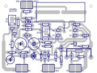
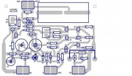
I couldnt help it, my usual foolishness, I had to try
I rearranged Q1,2,3,4 just a small bit
and a bit around Q6
and some ....
btw, OS has allowed me to do it
but better check for errors
as I said to ossie, Im not saying its better, but maybe only easier to DIY it
I couldnt help it, my usual foolishness, I had to try
I rearranged Q1,2,3,4 just a small bit
and a bit around Q6
and some ....
btw, OS has allowed me to do it
but better check for errors
as I said to ossie, Im not saying its better, but maybe only easier to DIY it
Attachments
- Status
- This old topic is closed. If you want to reopen this topic, contact a moderator using the "Report Post" button.
- Home
- Amplifiers
- Solid State
- The MONGREL (supersym II)