Thanks a lot OS!
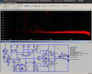
You could say it is a Rush... Here is a schematic with it grafted on to your PX. No mysterious unpredictable harmonics! The RC comp resistor can be increased for better specs, but there will be a resonance in the loopgain.
- keantoken
You could say it is a Rush... Here is a schematic with it grafted on to your PX. No mysterious unpredictable harmonics! The RC comp resistor can be increased for better specs, but there will be a resonance in the loopgain.
- keantoken
Attachments
Hey OS, these caps look really interesting. Not SILVER mica, but mica nonetheless.
SOSHIN ELECTRIC CO.,LTD. -PRODUCT INFOMATION-
Got me thinking, maybe SMD pads should be included for compensation caps?
- keantoken
SOSHIN ELECTRIC CO.,LTD. -PRODUCT INFOMATION-
Got me thinking, maybe SMD pads should be included for compensation caps?
- keantoken
Finished my AX/BX PB60 documentation update.
Those mica's would be REAL cool to SMD (solder direct) B-C for the miller .... no PCB trace required. As of now, I DO keep the miller VERY close to the VAS devices.
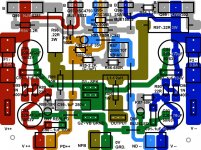
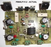
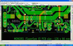
I have finalized my standard documentation package with all the "mongrels". I will include a high quality photo like SNG001 did in his PDF for the PS80. This photo will coincide with the schema/overview for ease of construction. Below is an example (pix 1/2 - PB60LP).
The AX/BX are done but are without pictures (tomorrow). I redesigned these "low end" projects .. ha ha... to accept your "junk parts".The AX was almost the top performer in WAHIB's amp shootout with 200ppm THD @ 1K/40v p-p , so "low end" might be debatable ???
Even with new parts, 2 voltage boards can be had for $25USD. Total for a stereo pair AX or BX + PB60LP's would set you back $45-50USD ...much less if you clean out your junk drawers..
All ZIP's that end in "final" are built and have been throughly ABUSED in the "DOGHOUSE". (CXVB1.2 is next)
BTW , the below PB60 is an EXACT copy of your power board(s).. keen , use as a guide when you get your box...
OS
Hey OS, these caps look really interesting. Not SILVER mica, but mica nonetheless.
SOSHIN ELECTRIC CO.,LTD. -PRODUCT INFOMATION-
Got me thinking, maybe SMD pads should be included for compensation caps?
- keantoken
Those mica's would be REAL cool to SMD (solder direct) B-C for the miller .... no PCB trace required. As of now, I DO keep the miller VERY close to the VAS devices.
I have finalized my standard documentation package with all the "mongrels". I will include a high quality photo like SNG001 did in his PDF for the PS80. This photo will coincide with the schema/overview for ease of construction. Below is an example (pix 1/2 - PB60LP).
The AX/BX are done but are without pictures (tomorrow). I redesigned these "low end" projects .. ha ha... to accept your "junk parts".The AX was almost the top performer in WAHIB's amp shootout with 200ppm THD @ 1K/40v p-p , so "low end" might be debatable ???
Even with new parts, 2 voltage boards can be had for $25USD. Total for a stereo pair AX or BX + PB60LP's would set you back $45-50USD ...much less if you clean out your junk drawers..
All ZIP's that end in "final" are built and have been throughly ABUSED in the "DOGHOUSE".
(CXVB1.2 is next)BTW , the below PB60 is an EXACT copy of your power board(s).. keen , use as a guide when you get your box...
OS
Attachments
Last edited:
PB120LP Ver.2 PCB
Hi,
I have made some minor changes to the PB120LP. The Ver.1 board is being built by Repeet and I found more clearance are need for some resisters. I made some minor changes:
More clearance for R85 & R88.
Relocate R98 & R99 so that they no longer live under the inductor.
Space for bigger output inductor.
Fatter ground trace.
Bigger on-board filter caps - snap-in types up to 25mm dia.
Deleted the Capacitor-multiplier option.
The board is slightly smaller.
I will create the BOM & PDF for the new ver 2 of PB120LP.
Cheers, Stanley
Attachments
Hi,
I have made some minor changes to the PB120LP. The Ver.1 board is being built by Repeet and I found more clearance are need for some resisters. I made some minor changes:
More clearance for R85 & R88.
Relocate R98 & R99 so that they no longer live under the inductor.
Space for bigger output inductor.
Fatter ground trace.
Bigger on-board filter caps - snap-in types up to 25mm dia.
Deleted the Capacitor-multiplier option.
The board is slightly smaller.
I will create the BOM & PDF for the new ver 2 of PB120LP.
Cheers, Stanley
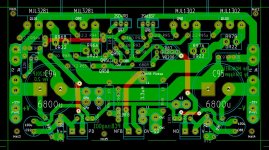
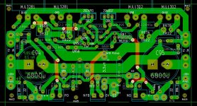
Some layout adjustments.... I HATE D96/97 "crooked" !! Move c88/92 right next to the voltage board interface euroblocks , line up the diodes (d96/97) and the resistors (r75/78) vertical near mounting points.
C99/r99 swap with the G1 takeoff point , as close to the OP coil as possible and long jumper over R96b can be 2 short ones , first right above 96b. You dont need the big 6800uF's on board if you have such a big offboard supply like the PS80/100 , shrink to 1k/63v -12.5 -18mm for more layout room to center G1/2 .. this is more important than big caps , especially for G1 (big "dirty pulses from OPS),
you might even add the blueled (V- 68k Resistor/high efficiency).
Otherwise all is good.
What is the CAD software used ?? SNG.... I only use "head" now.

OS
Last edited:
Hi OS,
Thanks for the tips, I will see if I can change the pickup point for G1.
I did a quick change to D97 so that it is no longer crooked.
I use KiCad which is a free software. I found that the learning curve is not too bad, may be because I used the DOS version of Protel AutoTrax before. The default libraries are good but I already added quite a few of my custom footprints to the user library.
Cheers, Stanley
Attachments
OS, I got the box today.
Is there any simple way to clamp outputs to a heatsink using ordinary household materials?
- keantoken
Kool... USPS is dang kwik!!
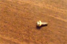
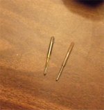
I use these... they are $1-2 apiece at a local ACE hardware store... (below pix1)
for doing either low or high power amps you need 1 - 6-32 tap and 1- 4-40 tap.
you ask the helpful hardware man to select the 2 drill bits for these taps ,...drill the holes and the 4-40 / 6-32 screws cost $0.10 cents apiece.. the NJW's mate with the 6-32 screws , the MJE's mate with the 4-40's along with the right insulator (pix2). the ksa3503 can be directly screwed to the HS.(with HS grease). the taps can be used with oil in the holes ... vice grip , slow turn .. back out , slow turn... you get factory results.
If you must , you can directly screw the NJW's to the HS with metal tapping screws using a mica or silicone insulator. the MJE's are more complicated with the shoulder washer shown in ( pix 2). I would suggest the taps from ace as they give the best results.
PS.. you can obtain the shoulder washers for the mje's from used PC power supplies .. usually 4 in each.
If you need more info I will PRESENT my tapping efforts NEXT on this thread... must do my PB60 "doghouse" amp..
OS
If you lack
Attachments
Last edited:
Gifted enthusiast and valued contributor...
Regarding the last post ,member Keentoken is highly appreciated for his excellent contributions to DIYA . I believe he will go very far , this is why I gave him AMPS. If any member reading this would be kind enough to help by donating any power supply- caps/ trafo's .. etc. to him , I feel the "payback" would be twofold. This young man might even possibly surpass B. Cordell or other audio/EE "giants" at his present learning curve.
I did not present this to "beg" or to embarrass , but feel the community would benefit, as this is a good "investment".As Ed LaFontaine "invested" in me , I must invest in others with merit. We all could gain better designs as a "side benefit".
OS
Regarding the last post ,member Keentoken is highly appreciated for his excellent contributions to DIYA .
I believe he will go very far , this is why I gave him AMPS. If any member reading this would be kind enough to help by donating any power supply- caps/ trafo's .. etc. to him , I feel the "payback" would be twofold. This young man might even possibly surpass B. Cordell or other audio/EE "giants" at his present learning curve.I did not present this to "beg" or to embarrass , but feel the community would benefit, as this is a good "investment".As Ed LaFontaine "invested" in me , I must invest in others with merit. We all could gain better designs as a "side benefit".
OS
PB120LP Version 2
Hi OS,
I have implemented all your suggestions.
The size of the filter caps have no impact on the pickup point for G1 & G2 as the inductor occupies the centre of the output trace. I made an custom footprint for the filter caps so that one can use 7.5mm or 10mm lead spacing for C94 & C95 = more flexibility.
BTW, you have duplicate component designators on PB60LP like you have two R87 & two R88, so I made up my own for the LED resistors.
Cheers, Stanley
Some layout adjustments....
C99/r99 swap with the G1 takeoff point , as close to the OP coil as possible and long jumper over R96b can be 2 short ones , first right above 96b. You dont need the big 6800uF's on board if you have such a big offboard supply like the PS80/100 , shrink to 1k/63v -12.5 -18mm for more layout room to center G1/2 .. this is more important than big caps , especially for G1 (big "dirty pulses from OPS),
you might even add the blueled (V- 68k Resistor/high efficiency).
OS
Hi OS,
I have implemented all your suggestions.
The size of the filter caps have no impact on the pickup point for G1 & G2 as the inductor occupies the centre of the output trace. I made an custom footprint for the filter caps so that one can use 7.5mm or 10mm lead spacing for C94 & C95 = more flexibility.
BTW, you have duplicate component designators on PB60LP like you have two R87 & two R88, so I made up my own for the LED resistors.
Cheers, Stanley
Attachments
Member
Joined 2009
Paid Member
Shipping might not be viable from here, but I'd be happy to contribute some $$ to someone closer if they'd be willing to purchase and send kean some goodies.
Steve.
Steve.
Regarding the last post ,member Keentoken is highly appreciated for his excellent contributions to DIYA .
I did not present this to "beg" or to embarrass , but feel the community would benefit, as this is a good "investment".As Ed LaFontaine "invested" in me , I must invest in others with merit. We all could gain better designs as a "side benefit".
OS
Kean,
I have more tranny's to spare. Contact me by pm with your needs.
We are all in this together. I admire the effort you put into this.
There should be no roadblocks...
OS, did you receive my request for info? No hurry, just confirm. Thanks
I did , I will have to look around .. there are so many convention halls around here (gatlinburg/pigeon forge, TN) .. it is ridiculous. (hundreds)
OS
Member
Joined 2009
Paid Member
here is a quick guide to tapping
Untitled Document
I haven't tapped a thread since high school but we were specifically taught not to do what is recommended here (assuming I've read this document correctly) - don't thread the hole all in one shot.
The approach I was taught is to
a) lubricate the tap (grease/oil is fine)
b) turn the tap clockwise a turn or so and stop
c) back off by turning the tap counter-clockwise a fractional turn, in steel you can easily feel a 'click' as the tap cuts off the burr/swarf it's just created and this cleans out the thread to allow you to cleanly repeat step b) & c) until you are done
when you do it this way you'll find that the tap doesn't get stiffer and stiffer to turn as it builds up crud but should instead present the same resistance each time you repeat the cutting process.
never force the tap.
TAP .. TAP..tapping pictures..
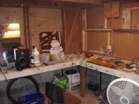
I was in the "Doghouse" tonight (attachment 1).
First I lined my PB60 up to an old hammond PS heatsink , centered it and decided on 3/4"(to-126) - 7/8" ( to-220) - 1-1/8" (to-3p) heights for my output stage devices.
(attachment 2). My board surface will be 3/8" (10mm)up from the
bottom of my heatsink.
The small devices (to-126 /to-220) get drilled and tapped for 4-40 screws and the outputs are drilled and tapped for 6-32 screws.
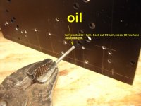
(attachment 3). It is VERY important to choose the proper drill size .... A GUIDE - Widell Industries Tap Drill Sizes
and to lubricate well. After the holes are drilled insert tap and turn 2-3 turns , back out one ... when deeper go in 1 turn back out 1/2 . Occasionally totally remove tap to clean and relubricate. When all done with tapping ,give the Virgin holes their first screws to "break them in".... Also , very SLIGHTLY countersink each hole with a larger drillbit to remove "burrs". A final check of collector to heatsink continuity is recommended to avoid disaster.
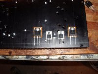
(attachment 4) is the completed retrofit all done with primitive tools. this amp has to put up with a lot of abuse (testbed) , so I decided to do it right the first time.
The proper insulators are single mica/teflon/silicon for the to-3p devices , a shoulder washer/mica for the to-220's and nothing is required for the Vbe (2sc3503). Man, fall is beautiful (last PIX) .. the "Doghouse" is in a monster tree forest...
BIGUN , ABSOLUTELY!! DO NOT break the tap... ARgggggg!
OS
I was in the "Doghouse" tonight (attachment 1).
First I lined my PB60 up to an old hammond PS heatsink , centered it and decided on 3/4"(to-126) - 7/8" ( to-220) - 1-1/8" (to-3p) heights for my output stage devices.
(attachment 2). My board surface will be 3/8" (10mm)up from the
bottom of my heatsink.
The small devices (to-126 /to-220) get drilled and tapped for 4-40 screws and the outputs are drilled and tapped for 6-32 screws.
(attachment 3). It is VERY important to choose the proper drill size .... A GUIDE - Widell Industries Tap Drill Sizes
and to lubricate well. After the holes are drilled insert tap and turn 2-3 turns , back out one ... when deeper go in 1 turn back out 1/2 . Occasionally totally remove tap to clean and relubricate. When all done with tapping ,give the Virgin holes their first screws to "break them in".... Also , very SLIGHTLY countersink each hole with a larger drillbit to remove "burrs". A final check of collector to heatsink continuity is recommended to avoid disaster.
(attachment 4) is the completed retrofit all done with primitive tools. this amp has to put up with a lot of abuse (testbed) , so I decided to do it right the first time.
The proper insulators are single mica/teflon/silicon for the to-3p devices , a shoulder washer/mica for the to-220's and nothing is required for the Vbe (2sc3503). Man, fall is beautiful (last PIX) .. the "Doghouse" is in a monster tree forest...
BIGUN , ABSOLUTELY!! DO NOT break the tap... ARgggggg!
OS
Attachments
- Status
- This old topic is closed. If you want to reopen this topic, contact a moderator using the "Report Post" button.
- Home
- Amplifiers
- Solid State
- The MONGREL (supersym II)