Polyester is also known as Mylar, everywhere I've read.
MKS is polyphenylene, hardly heard of it.
More info:
Input Capacitors for Headphone Amps
Polyester/mylar is the least preferred film type for audio (but of course still better than non-film caps).
- keantoken
MKS is polyphenylene, hardly heard of it.
More info:
Input Capacitors for Headphone Amps
Polyester/mylar is the least preferred film type for audio (but of course still better than non-film caps).
- keantoken
Thanks KT,
Nice doc, I quote a few lines here:
"Also, the dielectric film material matters: in decreasing order of preference for use in an audio signal path, the main types are polypropylene, PPS and polyester. You shouldn’t go any farther down the scale than polyester for signal path caps under any circumstances.
The better the capacitor, the bigger it tends to be, physically. The previous section also shows us that higher cap values are also better than lower values, which increases physical cap size as well. Since board space is limited, you may have to compromise on the input capacitor’s quality. If your board space limits you to a choice between a 1.0 µF metalized polyester and an 0.1 µF polypropylene, the polyester might actually be the better all-round choice."
A small 4.7uF film cap is always handy for different DIY projects.
Hi OS,
Thanks for the prompt reply.
I have a few questions with regards to the component value?
I referred to the schematics with voltage that you post earlier.
R2 -- -- resistor, 68K (33K on schematics)
R19 -- -- resistor, 82 (68 on schematics)
R20 -- -- resistor, 47 (33 on schematics)
R23 -- -- resistor, 270K (330K on schematics)
R24 -- -- resistor, 47 (33 on schematics)
R25 -- -- resistor, 82 (68 on schematics)
C7 -- -- capacitor, 47pF 250v (33pF on schematics)
C9 -- -- capacitor, 47pF 250v (33pF on schematics)
Can you please clarify which one (the attached schematics or BOM) is correct?
Cheers, Stanley
If you want what I have use the attached schematic. I apologize for the discrepancy , but I am still working on perfection for both voltage ranges.
At 42 volts all is well , in fact amp stays on spec until it reaches +/- 15v as the PS discharges ... bias spikes by a couple mV then amp collapses as rails go below 10V.
What I will (or possibly change) ...
1. Set the best(higher) amp gain for the 70-75V setup R1/4 to 680R and R10/11 to 33R , it will stay at the same compensation bode plot (gain of @38).
2. Set a lower more reasonable gain for 40-50V use, R10/11 to 56R ,1/4 kept at 820R , R2/5 to 27K (gain of @30).
3.Adjust the cascode voltage to reach a "happy medium" between voltage ranges. At 40v cascode voltage is under 10V , this could be fine for FET's and maybe even the BJT's but should be optimized (12-15V)for both voltage ranges. changing this will have NO effect on the sound , just the operating conditions that the semi's encounter.
What I must research and document,and adjust...
A. Adjust input pair(CCS adj. for optimum current , this also affects VAS current and main OPS bias but there is enough range there(Vbias) to handle the range of 1- 1.5+ mA per input transistor.
B. trim "LS adjust" with scope .. this balances the waveform between the pair , especially at low frequencies.
After living with it for a day , it does have a very small turn on/off thump, not enough to see on the woofer but barely audible.. it does exist. Another observation , as the rails collapse , there is no squeal or strange noise ... just a static distorted sound as you lose those remaining volts (7v and down to 0V)
What it does not have.. is ANY audible noise and hum , no thermal problems (VAS stays cool on both 45V and 75+V even after abuse) , rock steady main Vbias with 2mv max spread on 5 watt emitter resistors.
I have some unique problems .... My 80K of 20 year old Nichicon filter caps are getting bulge(s) in the middle (they are failing) I must build the PS100 with 8 new panasonic 80V units soon
 And I was running all these test through my MOV surge protector .. I have to design a new soft-start like ...NOW!!
OS

$3.00 ea. @ Apex JR.
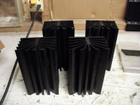
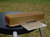
How can I get 8 of these ? I can pay 10/1/10 but do they trade ?? I have the 4 monster stealth heatsinks up for grabs.. (below)
Another thing that bothers me.. I have those 2 supersyms with 16 pair good OP's that I really want to give Keentoken , if he will wait ,on 10/1, I will have many AX and GX PCB's ... maybe a package to send him , I really want to do this but shipping/$$ are a problem.. I am ISOLATED (except for the "cop-caller" a mile away). These amps are WAyyy better than supersyms.
look at "monster sinks" , probably below 0.1 C/w.
OS
Attachments
OS, pardon me, but something in me is still stubbornly revolting against the 330p input cap. Consider when the volume pot is at a low setting. Say it's a 50k pot. Say the input impedance is now 45k at low volume. The -3db point for a 45k, 330pF LP filter is 10khz!
The 330p cap improves stability and HF characteristics at the OLUG point usually in sims, but I've never needed more then 22pF there. If I were to LP the input to soften potentially dangerous input signals, I would put the LP before the input pot, not after so that changing the pot didn't change the HF characteristics of the amp.
So I would change C4 to 22pF at most, and put any LP before the volume controls.
- keantoken
Substitute for A1381 & C3503
Thanks OS,
I will wait for your update.
Today I went to the local electronic shop & they don't stock the 2SA1381 & 2SC3503. I bought the Toshiba equivalents - 2SA1360 & 2SC3423.
The specifications looks very similar to the A1381/C3503 - they are 150V/200MHz devices and the Cob are 1.8pF.
I will etch the PB120 this weekend. I live in suburban Sydney & my neighbours are only 20 feet away - 100 to 120W is plenty for me;-)
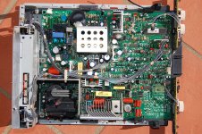
BTW I opened an old (circa 1996) LG monitor, hoping to score some useful transistors. I found three pairs of A1659/C4370 - 160V/1.5A/100MHz/20W/30pF and they should be useful as drivers. Again there are heaps of mylar cap & a few IRF VFETs.
Cheers, Stanley
What I will (or possibly change) ...
1. Set the best(higher) amp gain for the 70-75V setup R1/4 to 680R and R10/11 to 33R , it will stay at the same compensation bode plot (gain of @38).
2. Set a lower more reasonable gain for 40-50V use, R10/11 to 56R ,1/4 kept at 820R , R2/5 to 27K (gain of @30).
OS
Thanks OS,
I will wait for your update.
Today I went to the local electronic shop & they don't stock the 2SA1381 & 2SC3503. I bought the Toshiba equivalents - 2SA1360 & 2SC3423.
The specifications looks very similar to the A1381/C3503 - they are 150V/200MHz devices and the Cob are 1.8pF.
I will etch the PB120 this weekend. I live in suburban Sydney & my neighbours are only 20 feet away - 100 to 120W is plenty for me;-)
BTW I opened an old (circa 1996) LG monitor, hoping to score some useful transistors. I found three pairs of A1659/C4370 - 160V/1.5A/100MHz/20W/30pF and they should be useful as drivers. Again there are heaps of mylar cap & a few IRF VFETs.
Cheers, Stanley
Attachments
A1360/C3423
Hi Hugh,
I bought mine from WES in Ashfield - WES Components
2SA1360 is $1.40 each
2SC3423 is $1.70 each
I only bought a couple of each type, both are Toshiba 'Y' grade.
Cheers, Stanley
Hi Hugh,
I bought mine from WES in Ashfield - WES Components
2SA1360 is $1.40 each
2SC3423 is $1.70 each
I only bought a couple of each type, both are Toshiba 'Y' grade.
Cheers, Stanley
OStripper posted:
How can I get 8 of these ? ... but do they trade ??
http://www.apexjr.com
Steve is one of the good guys. He sells surplus, a lot of electronics. He has split orders for me in the past, sending portions to 2 different locations.
Steve has a link in the vendor furum here.
PCB variant for MONGREL ...
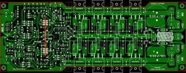
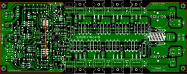
Next project will be this Symasym II , it's an very , very good sounding amplifier and I will invest some money to build a pair . I layout PCB for PB250 schematic , and possible some error regarding PCB , please help me to make the correct one .
Regards Alex .
Next project will be this Symasym II , it's an very , very good sounding amplifier and I will invest some money to build a pair
. I layout PCB for PB250 schematic , and possible some error regarding PCB , please help me to make the correct one .Regards Alex .
Attachments
Next project will be this Symasym II , it's an very , very good sounding amplifier and I will invest some money to build a pair
Regards Alex .
You say "it is good sounding" , did you prototype??
Split the ground , man. The main ground (G1) is only for the main big caps (4700-10k) the associated HF caps (.1uF@100-250v) , and the zobel cap. The capacitance multiplier , it's caps and the voltage stage have a separate ground (G2)... this feature allows the preferance of having the big spikes from the big caps on the PB250 go to the first reservoir on a PS such as the PS100 , the G1 could go to the second reservoir after the R or L on the main power supply(CRC or CLC style). If you lack something like that , you could always run G2 to a 4.7 to 10R resistor and then to the main reservoir.
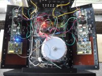
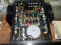
2nd day of hard testing and MILLING. It is all together now , I don't have to worry about someone getting electrocuted anymore. Big , lunky stealth case is much lighter after 1 less toriod and minus 4 -5lb heatsinks ... could actually be under 60lbs.
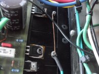
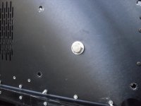
Stupid Genesis never properly grounded their heatsinks (pix 3) ,Anodized heatsinks do not conduct between them,
all they did was ground the hinge for the whole assembly .I fixed that-DIRECT earth. (Pix 4) is the huge 3/8 X 5" bolt to hold the 30lb toroid in there.Sg001 your replacement VAS semi's should be more than adequate.
OS
Attachments
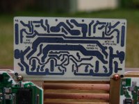
I have etched the PCB for the PB120 and test-mounted the PCB onto the heatsink. I may start drilling & mount the parts that I got in my parts bin.
Nice boardwork, SNG. What do you use for etchant ? HCL/H2o2??
OS
PCB etchant
OS,
I use Ammonium Persulphate
The alternative to Ferric Chloride. Mix contents (400 grams) with 1.5 litres of hot water to etch copper board approximately 500sq/cm.
It costs $13 for 400g, I used one teaspoon worth of crystal to etch the PB120, so 400g last a long time. It make a clear solution & it is not as corrosive as HCL.
Attached is the link to Australian supplier and you can look the MSDS on that site. Ammonium Persulphate - 400gm - Jaycar Electronics
Cheers, Stanley
Nice boardwork, SNG. What do you use for etchant ? HCL/H2o2??
OS
OS,
I use Ammonium Persulphate
The alternative to Ferric Chloride. Mix contents (400 grams) with 1.5 litres of hot water to etch copper board approximately 500sq/cm.
It costs $13 for 400g, I used one teaspoon worth of crystal to etch the PB120, so 400g last a long time. It make a clear solution & it is not as corrosive as HCL.
Attached is the link to Australian supplier and you can look the MSDS on that site. Ammonium Persulphate - 400gm - Jaycar Electronics
Cheers, Stanley
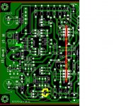
....after routed again the last PCB will be .No prototype until next week .....
Regards Alex
Hi AlexMM,
Nice layout, I like the idea of using 4x 1R as emitter resistor.
I have not checked the board trace by trace. I have the following suggestions:
(1) The Ground pin of the input connector should not be connected to G1, it should be connected to 33K (light-green trace).
(2) The two Green LED can be moved a few mm towards the LEFT to make more clearance for the small heatsink.
(3) The Q5 & Q6 can be moved a few mm towards the LEFT & a C-B bypass capacitor (5600pF) can be added.
(4) The label for Ground G1 & G2 are different from that of OS's. OS refered G1 as the noisy ground for Zobel & onboard cap, G2 is the clean ground for the VB.
Cheers, Stanley
Attachments
Last edited:
Have you considered the 3pin input as adopted by Jens for the Leach clone?
It offers lots of flexibility for connecting a source and doing initial testing.
It has a Signal Ground pin, a DC coupled pin going straight to 820r and an AC coupled pin going to 4u7F
The three pins are 0.1inch pitch and can use a 0.1inch 2female plug to short out the various unwanted options.
It offers lots of flexibility for connecting a source and doing initial testing.
It has a Signal Ground pin, a DC coupled pin going straight to 820r and an AC coupled pin going to 4u7F
The three pins are 0.1inch pitch and can use a 0.1inch 2female plug to short out the various unwanted options.
- Status
- This old topic is closed. If you want to reopen this topic, contact a moderator using the "Report Post" button.
- Home
- Amplifiers
- Solid State
- The MONGREL (supersym II)