A 33 ohm resistor in series with C1 or the "cap mod" works. That is assuming that by the time the amp is on the PCB, we will have any control over resonances at 200MHz!
The file is uploaded! Look in the Uploads folder at OS's website for BWV973.mp3, and please tell me what you think! I may be able to improve the sound by rendering differently.
- keantoken
Just keep the amp away from the PC.

Heard the mp3 , good. I play those classic synths (minimoog , ARP) on a keyboard.
OS
OS, any chance you could do a "parts mirror" for the PB60LP ?
20 MINUTES...done.
It is in the "PB60LP_complete.zip"
A hint , after ironing and soaking the mirror on top , spray some clear Lacquer (acrylic based) to "set" the labeling.
OS
Attachments
A hurricane passed nearby my house yesterday and the gale upended my room. Nah, it was just me. I was looking for my Switched-On Bach record, it's disappeared. I can't bear the thought of it slowly crumpling into a morbid shape under the piles. On the way I scavenged a bunch of old PCB's to get them out of the way. Got an Ero MKC polycarbonate cap, from a 1979 TV along with tons of nearly useless nF range film caps. I wonder why I kept the electrolytics from 1979...? I was surprised though, the TV was still working, without any repair work I could see, up until about a year ago.
It was then that I noticed that the soundstage of my speakers had improved... It's not just sound-emitting circles anymore. I am guessing that the reflections from the great pile occupying most of the room was giving the sound little free airspace.
However, I think my crappy Xplod car amp is unstable... Every time I listen to music it all sounds different. Usually it sounds bad, but there are some good days... Anyways I want to get a proper amp working, then I'll gut it, use the switching supply inside and try to build my own amp... Maybe.
Okay, 1 other person downloaded that file. Who might that be...?
- keantoken
However, I think my crappy Xplod car amp is unstable...
I WILL keep my promise , because when I have my PB250/CX1.1 and the new one (PS100) , the BIG power board , the old one will find your home. With your "cap trick" on LT , I have hit the "next level". It has shown me why the DX/aksa55 sounds as it does and how all the others stack up. Which means I "owe you".
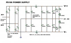
Below is the "BIG" power board .. 100,000uf is the max you can stuff it with , 50A bridge, CLC layout , snubbers , and red/blue leds so you won't die playin' with it. VERY expensive to do 100kuF - (70$-100$). If you use it for the little amps (PB60LP) or run the big one at under 60-0-60V you can fit 18k X 8 ...
144,000uf ($104). For audiophile use this should be good for both power boards. I am poor , so I am just going to buy 8 /6800-8200uf units .. I guess 54k + the 20k on my powerboards will just have to do. One other note , board is setup for this bridge : GBPC5010W-G Comchip Technology Bridge Rectifiers
Any fairchild 25-35A bridge has the same lead spacing.
"PS100_complete.zip is the "package" .
OS
Attachments
Last edited:
That rectifier pad looks like you could add more vias to make it compatible with many more rectifiers. Same with filter caps, and would it be possible to add pads for local bypass to each one? I find a lot of SIP type rectifiers in junk amps, sometimes attached to a heatsink. Does the rectifier fit in the bottom of the board, possibly for fitting to the main heatsink? Also, could you allow for use of a common-mode choke?
- keantoken
- keantoken
That rectifier pad looks like you could add more vias to make it compatible with many more rectifiers. Same with filter caps, and would it be possible to add pads for local bypass to each one? I find a lot of SIP type rectifiers in junk amps, sometimes attached to a heatsink. Does the rectifier fit in the bottom of the board, possibly for fitting to the main heatsink? Also, could you allow for use of a common-mode choke?
- keantoken
I made the rectifier pads even bigger with the snubbers spaced out even further. I really appreciate the B. Cordell and N. pass sections on the forum , they agree what I have made is the best "bang for the buck" (CLC) , as far as unregulated suppies go.
As far as local bypass for each big cap.. B_S!! That was discussed and dispelled (I read the whole B.Cordell-power supply interview). One good .1uF/250v at the main PS OP and another good one (low HF ESR) on the amp powerboard will be more than adequate.
If you drilled a 3/16" hole directly at the center of the bridge pads a 35-50A bridge could be thermally mated with the case or plate below if you spaced the board with 3/8" (10mm)spacers ... many, many options.Not everyone has the same parts , even as the mouser 50A bridges are just $3.79 !!
Chokes - Just about any mouser pre-formed from 3.3uH to 20uH will fit , as well as any you make your self. One could even put 2 -.1 / .33 R 10-15w resistors for a CRC setup.
OS
Tried to steal magnet wire from the primary of a microwave trafo... Did not work to good... Nicest stuff I could find was here: Colored Magnet Wire
I like the green stuff (16ga.)
For those who need to know , according to this formula ,
L= (d^2 * n^2)/(18d+40l)
where:
L is inductance in micro Henrys,
d is coil diameter in inches,
l is coil length in inches, and
n is number of turns.
Or , if you are lazy... Air Core Inductor Coil Inductance Calculator
So , for my PB60/250 .. 14 turns of that pretty green magnet wire at 25 X 25mm coil size = 3.37uH
For the PS100 , I went here to be lazy ... Pronine Electronics Design - Multilayer Air Core Inductor Calculator
and I get 20uH 2- layer inductors (with the same pretty green 16ga. wire)
with 8 + feet and 30 turns in 2 layers (approximate). So 1 spool of the 32ft. 16ga. will do the PS and both amps easy.
OS
Did not work to good... Nicest stuff I could find was here: Colored Magnet Wire I like the green stuff (16ga.)
For those who need to know , according to this formula ,
L= (d^2 * n^2)/(18d+40l)
where:
L is inductance in micro Henrys,
d is coil diameter in inches,
l is coil length in inches, and
n is number of turns.
Or , if you are lazy... Air Core Inductor Coil Inductance Calculator
So , for my PB60/250 .. 14 turns of that pretty green magnet wire at 25 X 25mm coil size = 3.37uH
For the PS100 , I went here to be lazy ... Pronine Electronics Design - Multilayer Air Core Inductor Calculator
and I get 20uH 2- layer inductors (with the same pretty green 16ga. wire)
with 8 + feet and 30 turns in 2 layers (approximate). So 1 spool of the 32ft. 16ga. will do the PS and both amps easy.
OS
Attachments
or start collecting dead pc psu's and pull the ferrite core chokes out of em
good idea!!
trafo centre tap twisted with AC secondary to the rectifier and passes through to be twisted with the DC after the rectifier to reach the junction of C5 & C9.ps100 power supply
Do not take the pulsing cap charging centre tap currents to the main audio ground. DO NOT!!!
Break the connection between C6 & C7. Since you have separated the two halves of the ground on the PCB, you also need to break the connection from C10 to C11.
Take the junction of C6 & C10 to the junction of C8 & C12. That becomes the PSU zero volts and take a lead from this output to your main audio star ground.
Last edited:
trafo centre tap twisted with AC secondary to the rectifier and passes through to be twisted with the DC after the rectifier to reach the junction of...
Normally, I'd lurk and chuckle about this one to myself, but I found it so funny that I thought I'd share.
I'm only barely able to read a schematic so the first time that I read this I did a double take. Then, I scrunched my face up and said "Okay, with the exception of 'trafo', I understand every word in that sentence... so why don't the words make sense to me when I try to put them together?".
It was at that point that I fell over laughing. You guys really do have secret language, don't you?!
Thanks for the lesson in humility!

Cheers,
Dave.
Hi,
I suppose it's part of the learning process.
Initially we learn to speak to our Mother. "I need fed", "I need to get my nappy changed"
Then it becomes "Mummy", "Daddy", "Hopital". How many have heard that and still recognise it as hospital?
Moving through the early years we learn to converse in a language that can be understood by our peers and parents/teachers.
Then the Foreign Languages start.
I place technical discussion in amongst that category. It is a "Foreign Language" to those outsiders that have not learned yet.
Just as Programming is a "Foreign Language".
Last edited:

Here we go.
The plot is impedance in ohms.
I think I was right! Interesting to note though, that at first the single Vbe multiplier was the worst option with lowest HF bandwidth and now it's nearly the best, and has the best HF bandwidth.
- keantoken
Thanks, very interesting. Seems that cap works as well as a darlington.
Could you post the sim file please, going to keep it for reference, who came up with the cap idea, it seems good. I will try it in a couple of minutes on one of my 1200w x 2 class G amp which I had factory built and was delivered this afternoon and see if it works good. As long as it doesnt oscillate it should be ok. They will be doing duty tonight in a nightclub replacing two previous versions of amps I hand built 3 years ago so hopefully all goes well.
BTW Os, I found a cool song on one of your webpages, something from my teen years but your version is a little modified, Ill have it played at the club tonight.
Hi OS
A few of points on the PB60LP PCB design.
In order to make everything fit inside my case I'm using C94/C95 as the 2nd half of the CLC, and they will be outboard 20,000uF caps. This raises the point that G1 tracks are long (and not very stiff in my mind). I believe the PCB design could be fairly easily modified to have G1 as a broad straight-line track directly from C94 to C95. This would stiffen G1 considerably in my opinion.
With G1 redesigned, then C96/C97 decoupling could be physically placed closer to the output transistors, eg connected to the rails located between the output and driver transistors and connected back to the new G1 track.
Also, I note the euro-conn NFB termination goes nowhere.
Your consideration on these points would be apreciated.
Craig
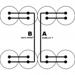
trafo centre tap twisted with AC secondary to the rectifier and passes through to be twisted with the DC after the rectifier to reach the junction of C5 & C9.
Do not take the pulsing cap charging centre tap currents to the main audio ground. DO NOT!!!
Break the connection between C6 & C7. Since you have separated the two halves of the ground on the PCB, you also need to break the connection from C10 to C11.
Take the junction of C6 & C10 to the junction of C8 & C12. That becomes the PSU zero volts and take a lead from this output to your main audio star ground.
OK , I split the grounds between the 2 banks on (attachment 1). "A" goes to the trafo CT and then to the chassis ground ? B is then separate and takes all the connections from both "G1 and G2" . Do A and B then connect separately to the chassis ? Also, is this change because of the CLC ? On the Quasi NMOS PS all amp grounds , the trafo CT , and all capacitor grounds terminate at a central star on the PS PCB.
OS
Also , would the main audio star ground be on the chassis ?
I DO take your advice in these matters VERY seriously , Andrew. While searching the forum for grounding info , your posts were everywhere.
OS
Attachments
Last edited:
Hi OS
A few of points on the PB60LP PCB design.
In order to make everything fit inside my case I'm using C94/C95 as the 2nd half of the CLC, and they will be outboard 20,000uF caps. This raises the point that G1 tracks are long (and not very stiff in my mind). I believe the PCB design could be fairly easily modified to have G1 as a broad straight-line track directly from C94 to C95. This would stiffen G1 considerably in my opinion.
With G1 redesigned, then C96/C97 decoupling could be physically placed closer to the output transistors, eg connected to the rails located between the output and driver transistors and connected back to the new G1 track.
Also, I note the euro-conn NFB termination goes nowhere.
Your consideration on these points would be apreciated.
Craig
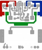
I already am redesigning the PB60LP (below) I can't go straight , but I can get a lot closer. NFB comes through a shielded wire with the shield at output potential. Wire can go beneath the board from L1 input to NFB terminal. Better than snaking it all across board.
OS
Attachments
- Status
- This old topic is closed. If you want to reopen this topic, contact a moderator using the "Report Post" button.
- Home
- Amplifiers
- Solid State
- The MONGREL (supersym II)