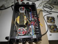
I picked up an Amber Series 70 with a dead right channel. Both fuses were blown in the right channel and after replacing them I powered up the amp again but they instantly blew. I'm thinking it's the 2N5686 and 2N5684 output devices but before I start throwing parts at it I was curious if anyone had any suggestions.
Any advice would be greatly appreciated.
Any advice would be greatly appreciated.
I´d start by checking the output devices with either a transistor checker or a multimeter set to continuity test (there are plenty of guides on how to test transistors and what readings you should get between pins available online). It´s probably also a good idea to do a visual inspection and check whether any resistors have scorched or any capacitors or transistors have blown. Also, check the power supply voltages are within a decent range.
A quick google didn´t bring many results for this amp and I checked all of the usual sites I use and could not find a service manual or schematic. If you can find one, it would help out a lot and give something for you to compare with.
A quick google didn´t bring many results for this amp and I checked all of the usual sites I use and could not find a service manual or schematic. If you can find one, it would help out a lot and give something for you to compare with.
If they are gone I would be asking why and if the original problem is still there.
After all you dont want to fit new components only for them to blow again.
Were you giving the amp some serious stick when it went ?
I would start off by checking speakers and leads for low resistance or a short.
Semiconductors rarely blow for no reason.
I usually fire my faulty amps up without output transistors in the circuit and feedback the VAS output into the LTP to make sure LTP, VAS and bias are working OK.
Last edited:
Thanks for the replies guys. I should have been more clear. The amp would instantly blow fuses in the right channel without speakers or RCA connections. The 2N5686 and 2N5684 output devices pulled out easily and I checked them. The 2N5686 both read the same but the 2N5684 read differently on my multimeter. I decided to swap the 2N5684 to see if powering it up it would then pop the left channel. I was surprised to see that it didn't. Now a logical person would have stopped here and ordered a new part. I being the dufus I am decided, "it's not popping fuses I wonder if I can give it a listen". I plugged everything up and turned it on. It sounded fantastic......for 30 seconds. Bright sparks started flying from the board of the left channel and I quickly unplugged the amp. The LM391N chip was all burned up and the cause of the fireworks. 
I'll post pictures later. I know it's beyond my skill level to fix the board, I may run by a shop and see what they think or just keep an eye on the classifieds for another Amber with a bad channel.
I'll post pictures later. I know it's beyond my skill level to fix the board, I may run by a shop and see what they think or just keep an eye on the classifieds for another Amber with a bad channel.
Amber Series 70
Hello:
")
After 3 decades operating a pair of Amber Series 70, I have found that one of the reasons for a LM391N failure is a wrong bias setting, which also will destroy the output devices, and in some cases the drivers also .
The bias must be adjusted to 150mA, as per the manufacturer settings.
After checking that all semiconductors including diodes and resistors are in correct working order, you should start with a low setting (6.2Kohm or so) of the 10Kohm potentiometer that together with the 3.9K resistor allow to adjust the bias properly. You must remove the + fuse and install the ammeter on the fuse holder legs in order to read the 150 mA after turning CW slowly the trimmer screw.
Before any adjusment, you should check the reading on the trimmer without AC applied, if this reading is more than 7Kohm is almost shure that bias setting is high in excess.
My Ambers sound icredible thanks to the use of audio grade components that were not available at its manufacture time, like Non polar caps bypassed with MKTs, and metal-oxide (1%) resistors. I do think that it is unnecessary to modify the original design.
I use both in Dual "half Stereo" configuration which increase the separation and perceptibly the power. Under these conditions and with its huge PS (64.000uF) the Amber outperform modern amplifiers costing a lot of more money.
I hope this can help to someone.
Thanks for the replies guys. I should have been more clear. The amp would instantly blow fuses in the right channel without speakers or RCA connections. The 2N5686 and 2N5684 output devices pulled out easily and I checked them. The 2N5686 both read the same but the 2N5684 read differently on my multimeter. I decided to swap the 2N5684 to see if powering it up it would then pop the left channel. I was surprised to see that it didn't. Now a logical person would have stopped here and ordered a new part. I being the dufus I am decided, "it's not popping fuses I wonder if I can give it a listen". I plugged everything up and turned it on. It sounded fantastic......for 30 seconds. Bright sparks started flying from the board of the left channel and I quickly unplugged the amp. The LM391N chip was all burned up and the cause of the fireworks.
I'll post pictures later. I know it's beyond my skill level to fix the board, I may run by a shop and see what they think or just keep an eye on the classifieds for another Amber with a bad channel.
Hello:
After 3 decades operating a pair of Amber Series 70, I have found that one of the reasons for a LM391N failure is a wrong bias setting, which also will destroy the output devices, and in some cases the drivers also .
The bias must be adjusted to 150mA, as per the manufacturer settings.
After checking that all semiconductors including diodes and resistors are in correct working order, you should start with a low setting (6.2Kohm or so) of the 10Kohm potentiometer that together with the 3.9K resistor allow to adjust the bias properly. You must remove the + fuse and install the ammeter on the fuse holder legs in order to read the 150 mA after turning CW slowly the trimmer screw.
Before any adjusment, you should check the reading on the trimmer without AC applied, if this reading is more than 7Kohm is almost shure that bias setting is high in excess.
My Ambers sound icredible
thanks to the use of audio grade components that were not available at its manufacture time, like Non polar caps bypassed with MKTs, and metal-oxide (1%) resistors. I do think that it is unnecessary to modify the original design.I use both in Dual "half Stereo" configuration which increase the separation and perceptibly the power. Under these conditions and with its huge PS (64.000uF) the Amber outperform modern amplifiers costing a lot of more money.
I hope this can help to someone.
They made a Lm391n-80 and the lm391n- 100. These are not made any more. If you can locate the -100 use this one instead of the 80.
regards
David
Hi David:
Efectively most people know that both models has been discontinued by NS, but the N100 anyone can buy to a few distributors yet.
Best wishes.
another issue will be to have a more proper VBE multiplier function that the 391 doesnt have and beyond other issues thermal runaway might also be a problem
I recall that someone in a Greek forum added an external VBE multiplier outside the 391 still this will require some digging to find
Kind regards
sakis
I recall that someone in a Greek forum added an external VBE multiplier outside the 391 still this will require some digging to find
Kind regards
sakis
Schematic for Amber Series 70
I probably was not clear about what I saying anyone can get a schematic for the Amber Series 70. The data sheet for a LM391N-100 containing information about this IC. Then, to make it easy for a amplifier designer, National Semiconductor then goes on and shows an application of the IC in an amplifier. The output transistors that they show that are added to the IC to make a complete amplifier are connected the same way as my Amber Series 70. This implies that the idea for the Amber amplifier was created by the engineers at National. If anybody wants to see this data sheet, do a google search for an LM391N. One of the responses from the search will be a free data sheet from alldata.com
I probably was not clear about what I saying anyone can get a schematic for the Amber Series 70. The data sheet for a LM391N-100 containing information about this IC. Then, to make it easy for a amplifier designer, National Semiconductor then goes on and shows an application of the IC in an amplifier. The output transistors that they show that are added to the IC to make a complete amplifier are connected the same way as my Amber Series 70. This implies that the idea for the Amber amplifier was created by the engineers at National. If anybody wants to see this data sheet, do a google search for an LM391N. One of the responses from the search will be a free data sheet from alldata.com
I have an Amber series 70 that I purchased new in 1984. As suggested by the operating instructions I left this amp turned on except when I moved to a house and when I tried other amplifiers in my sound system. In 2012, smoke started coming out of the amp and after shutting it off, I found one fuse was blown and one of eight plastic 0.022 uF capacitors which bypass eight 1000 uF capacitors had shorted and burned it shelf up. This was the source of the smoke and the reason why one of the fuses popped open. I repaced all eight of plastic caps with Polypropylene caps with the same 0.022uf value. Two of the 1000 uf caps had a high ESR (Equivalent Series Resistance) and were replaced. Then I noticed that the input blocking capacitor on each channel was a non polar aluminum electrolytic cap which is not a good audio capacitor.. Each of these two caps were replaced with metalized polypropylene capacitors.
These parts replaced made the Amber sound much better. But, I determined that the Amber is unusual in that it is an inverting amplifier. 99% of all amplifiers are non-inverting. So, I reversed both wires to each speaker and now the amplifier is one of the best amplifiers that I have ever heard.
These parts replaced made the Amber sound much better. But, I determined that the Amber is unusual in that it is an inverting amplifier. 99% of all amplifiers are non-inverting. So, I reversed both wires to each speaker and now the amplifier is one of the best amplifiers that I have ever heard.
Amber Series 70
Of course, it help.
I own a pair of Amber 70. that are used in Dual half Stereo too: Both amps. came with 470uF-50v polar capacitors. I replaced them with Nichicon Audio Grade non polar of the same value, by passed with MKT 0.1 uF 150v. All resistors were replaced with metal oxide 1% 1/4 w. because I did not found Metal Film which are a lot better. Emitter resistors were changed with metal oxide of better tolerances than the original ceramic ones. After all this the sound change was not significative driving the Mid-Hi panels of my Infinity RS 1b. I think due to the use of the non polar caps. In view of this poor result and knowing that units wth serial numbers after my ones, came with 1.000uF capacitors, I am thinking to replace the 470uF non polar with 1.000uF Nichicon Muse polarized ones. But I don`t know if changing the caps. value, other changes also I must do, like to change the diodes values to resist the capacitance increment surge.
The Ambers were built like tanks (28 lbs. for a mere 70 watt ?) with a huge: transformer, main caps and diode bridge, also with oversized output devices (300 w/50 amps. ea.) with care and normal maintenance can last for more than a century.
Does you pair came with 1.000 uF? If so, do you have the schematic to share?
Regards
Hello:
After 3 decades operating a pair of Amber Series 70, I have found that one of the reasons for a LM391N failure is a wrong bias setting, which also will destroy the output devices, and in some cases the drivers also .
The bias must be adjusted to 150mA, as per the manufacturer settings.
After checking that all semiconductors including diodes and resistors are in correct working order, you should start with a low setting (6.2Kohm or so) of the 10Kohm potentiometer that together with the 3.9K resistor allow to adjust the bias properly. You must remove the + fuse and install the ammeter on the fuse holder legs in order to read the 150 mA after turning CW slowly the trimmer screw.
Before any adjusment, you should check the reading on the trimmer without AC applied, if this reading is more than 7Kohm is almost shure that bias setting is high in excess.
My Ambers sound icredible
I use both in Dual "half Stereo" configuration which increase the separation and perceptibly the power. Under these conditions and with its huge PS (64.000uF) the Amber outperform modern amplifiers costing a lot of more money.
I hope this can help to someone.
Of course, it help.
I own a pair of Amber 70. that are used in Dual half Stereo too: Both amps. came with 470uF-50v polar capacitors. I replaced them with Nichicon Audio Grade non polar of the same value, by passed with MKT 0.1 uF 150v. All resistors were replaced with metal oxide 1% 1/4 w. because I did not found Metal Film which are a lot better. Emitter resistors were changed with metal oxide of better tolerances than the original ceramic ones. After all this the sound change was not significative driving the Mid-Hi panels of my Infinity RS 1b. I think due to the use of the non polar caps. In view of this poor result and knowing that units wth serial numbers after my ones, came with 1.000uF capacitors, I am thinking to replace the 470uF non polar with 1.000uF Nichicon Muse polarized ones. But I don`t know if changing the caps. value, other changes also I must do, like to change the diodes values to resist the capacitance increment surge.
The Ambers were built like tanks (28 lbs. for a mere 70 watt ?) with a huge: transformer, main caps and diode bridge, also with oversized output devices (300 w/50 amps. ea.) with care and normal maintenance can last for more than a century.
Does you pair came with 1.000 uF? If so, do you have the schematic to share?
Regards
other comments to my "Fuse Blowing Amber Series 70
I am the original owner of the Amber Series 70. Since this amplifier was bought in 1984 I know that the amp came with eight 1000 uF aluminum capacitors. These caps (4 in each channel) bypass the plus and minus secondary voltages. Two caps in each channel bypass the positive secondary voltage and the other two caps bypass the negative secondary voltage.
I do not have a schematic or any other service information. The data sheet for the LM391N can be downloaded. The information in this data sheet is helpful in determining the purpose of the passive components. The data sheet shows an application of the LM391N as a non-inverting power amplifier. My amp is an inverting amplifier.
Other owners have reported that the 1000 uF capacitors are not in their amplifier. Did Amber change the secondary voltage bypass capacitors from 1000 uF to 470 uF? Seems to me that this would have been a cost cutting move. Did Amber change the amplifiers from a non-inverting configuration to an inverting configuration? Not likely because each pc board would have be redesigned.
I used to work at Amber in the early 80's (if your amp has the initials "MLS" on any of the stickers inside, that's me), and I still have some of the schematics showing the progression of the series 70 design from the late 70's to the early 80's. None of the versions I am familiar with were inverting, unless the design changed after I left the company (pretty sure it didn't). Note, of course, that one of the channels becomes inverting when strapped mono mode is selected via the stereo/mono switch on the back. In stereo, however, both channels should be noninverting. The bypass capacitors were changed from 470uF to 1000uF in later designs in an effort to improve the sound (the opposite of a cost cutting move!). This change (and others) occurred around the time the layout of the amp was redesigned, with the heatsinks moved to the back, wood sides added, etc. Hope this helps!
-Mark S.
Hi Folks;
I have an Amber series 70 that had most of the fuses blown, even bypassed with wire! I have Fluke meter tested the outputs, drivers, and diodes and found all OK. Replacing fuses, The amp could not be brought up with the LM391n-100 's in their sockets.
I suspect both IC's to be bad. One IC measures 5 ohms from pin 15 to 16. It burned the 68 ohm resistors with installed in the other channel's driver board. The IC for THAT board read open from pin 15 to 16 but caused the output to swing to the positive rail.
The amp can be brought up to line voltage with the driver boards installed but without the IC's. Can I assume the IC's are bad...and are there substitutes that would work?
Attachments
Peter,
I am not aware of any source for original LM391s nor am I aware of any suitable substitutes. There seem to be some possible knockoffs available from China on e-bay and elsewhere but obviously that’s a crapshoot. I’ve been tempted to get some of them and run them (carefully!) across my test bench to see if they hold up and meet spec. If I do so I’ll be sure to post the results here. That being said I’m not sure I want to risk a cascading chip failure taking out an otherwise-good Amber amp! So we’ll see. In the end, your best bet may be to find a junker or “parts locker” Amber 70 or 50 on e-bay and scavenge any usable chips and other parts from it. Good luck!
-Mark S.
Hi Mark , I have a 70 in vgc . Are there any suitable substitutes for the 391s ? Also , are there any mods that can substantially improve sound ? I notice it runs quite cool compared to similar AB amps and given the limited heat sinks . What should the bias be set at ?Any biasing advice ?
Hi Guys;
Just a little update. I have received my 391 chips from an 'off shore' source. My amp had both chips defective, one open and the other shorted causing R 12 and R 13 to 'smoke'.
R12 and R13 in my amp were 100 ohm. I replaced them with 220 ohm resistors (my schematic shows 221 ohms unless I'm reading it wrong. Is there even such a value?) The amp powered up with the new chips and they held up even running the amp up to clipping into a dummy load. Bias was set according to the attached pdf, and all was good.....I thought.
There is a low level hum not noticed at first. Strangely, if only one input is connected ( L or R) there is no hum. Pretty sure it is a 60 Hz hum, ( from a grounding issue?) rather than 120 Hz, which would indicate a power supply issue(?). The amp has a central ground connection, but then breaks the 'star topology' rule with the input wiring.
Also; I am completely baffled by the mono/stereo switch; why feed the speaker output of one channel into the input of the other? Why not parallel the inputs?
Attachments
Paralleling the 2 channels only increases current capability. It doesn't increase the amount of current a speaker will draw.
Inverting one channel, then connecting the speaker between the hots of both channels, doubles the voltage put on the speaker. That probably doubles the amount of current in the speaker, if the output transistors don't limit it.
Inverting one channel, then connecting the speaker between the hots of both channels, doubles the voltage put on the speaker. That probably doubles the amount of current in the speaker, if the output transistors don't limit it.
- Home
- Amplifiers
- Solid State
- Fuse Blowing Amber Series 70