Nice bit of rendering for the board layout ")
IMHO while the output stage maybe be capable of the power out
The input and driver stage leave a lot to be desired for this kind
of power level and the number of output devices that is is expected to drive.
A VAS driver stage for 20 o/p devices would only give you a bandwidth of less
than 35khz at best... The gate charge just has no where to go.
Also the o/p devices are way to close to each other, just not enough thermal
mass around each device for this power level.
The diode in the emitter in the Vbe multiplier will help a small amount for compensation, but what you will find is it will not compensate correctly under load and under compensate, this type of biasing scheme is not suitable for such high power.
There are a number of other design errors in the input and driver stage.
Great job on the PCB layout, it looks OK, juts need to fix some design issues
and I think it will be OK.
Cheers
Anthony
in a professional amplifier and in levels of power by far lower than 400-500 W a wining design is not the amp it shelf ..... strip down the circuit ( of a typical AB design ) and you will realize that most amplifiers are based more or less on the same idea .
now what makes one amplifier better than one other is neither the schematic nor the pcb ...what makes the amplifier better is the supportive circuits that control and secure various stages of the amplifier .....
we have units doing that in many many ways and not always with succes ...either they protect the amplifier too much and kill all the sonics but at least poreserve stability or provide protection that fails under a few conditions ...
Using Dr Bora's sayings at this level of power the amplifier should be designed as idiot proof from every aspect ....
regards sakis
2SA968B/2SC2238B (25W,100MHz) 35mA, 4xIRFP240/9240
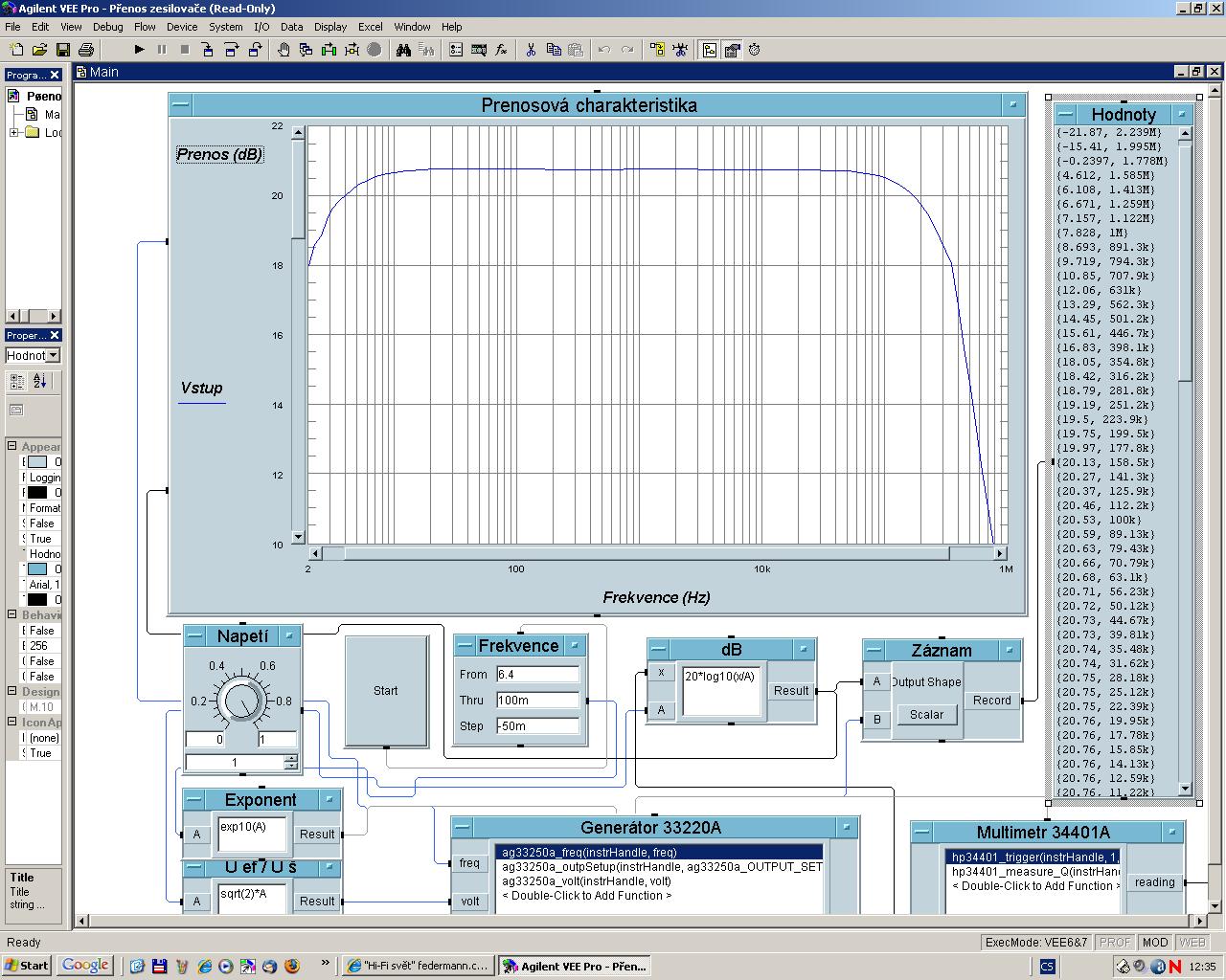
Bandwidth -3dB = 1,8Hz÷370kHz
Bandwidth -1dB = 3,2Hz÷200kHz
Bandwidth -0,1dB = 10Hz÷70kHz
This amp has no driver transistors, just VAS and paralleled output devices. It would be nice to see not the small signal frequency response, but power bandwidth, frequency response measured somewhere at -3dB of full output power.
This amp has no driver transistors, just VAS and paralleled output devices. It would be nice to see not the small signal frequency response, but power bandwidth, frequency response measured somewhere at -3dB of full output power.
Measured:
2Hz-3MHz
Input voltage 1V
Output voltage 10,9V/4Ω/1kHz (30W)
Is not practical to measure 60V/3MHz!!!
Last edited:
8 pairs and 2x500W
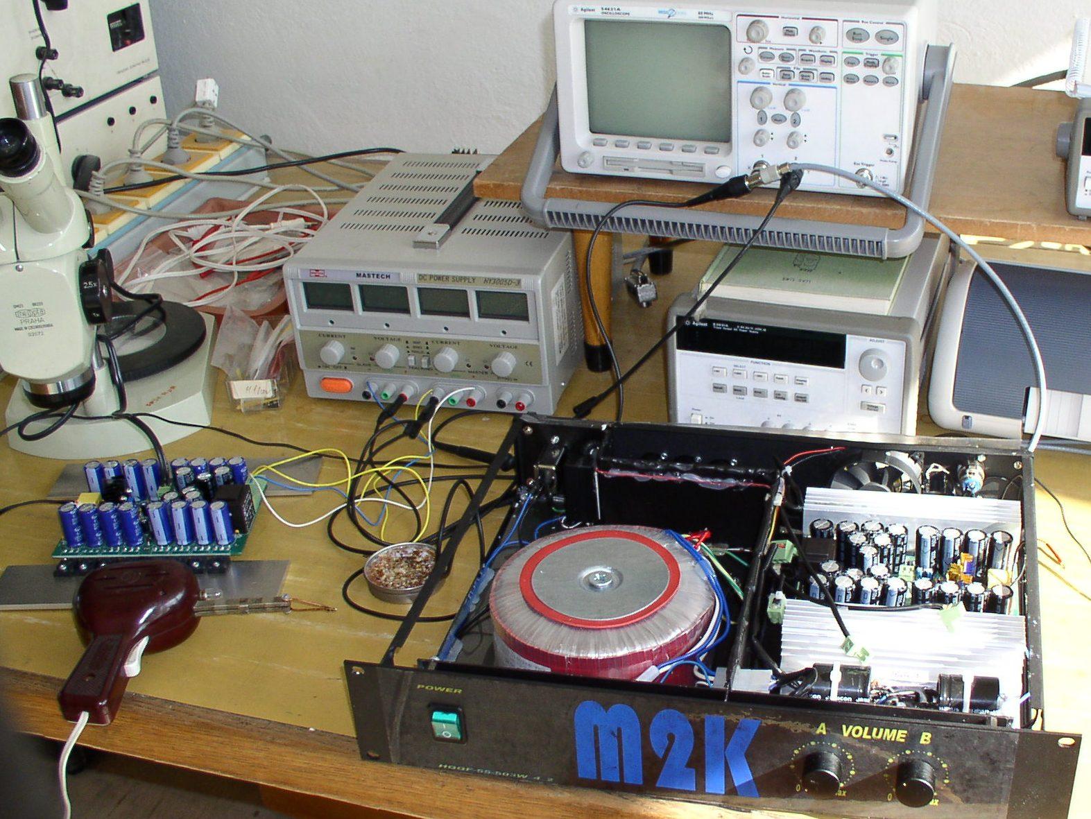
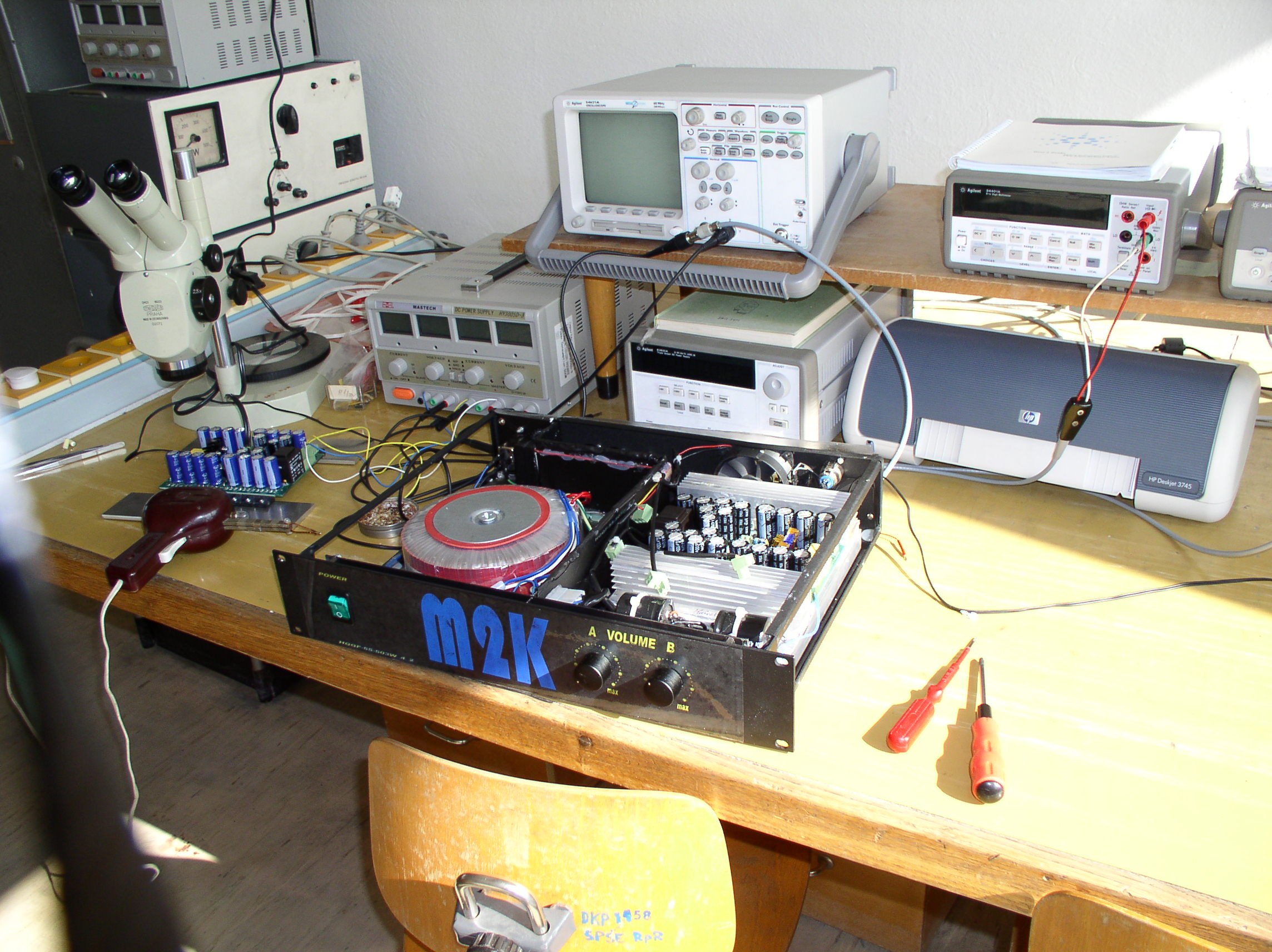
I am in doubt if any prototype of this amp exist, 'cause I think this photo is a Photoshop or Corel image done by inserting of CAD image to it. You can strong view it on superscription "M2K" and "Volume A, B".
There is no heavy cooler. And all your scheme is tricksy. I can only pressupose that it will explode by heat caused by performer transistors.
You need to get realistic here , 1 - 2kw with small heatsinks , cramped layout , and a very simple driverless LPT/VAS..... BURNING AMP... 
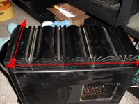
Below (attachment 1) , you will see what just 4 pair IRFP240/9240's needs for 800W dissipation. The 4 pair were spread out across the whole 17" of that monster and hit 50C with convective cooling only. If one was to use forced air ,more wattage could be successfully dissipated.
For 3-6 pair , at a minimum , a mje340/350 driver pair would suffice. I use 2sa1837 / 2sc4793 (much faster) or mje15032/33's (cheap , but stronger).
For 10 pair , wow ... definitely the mje15032/33's , gate protection diodes , 2 transistor precision VBE , and a proven LPT/VAS.
OS
Attachments
Federmann
Many members have commented on your amplifier design.
Many have complimented the work that you have done.
Others have made suggestions to improve the amp.
Their suggestions are based on a wealth of experience and knowlege of amplifier design.
So far all you seem to have done is defended your design as is.
Are you interested in improving this amplifier with the help and support of the members of this forum?
I feel that your stance is alienating other members if the last few posts are anything to go by!
Hi Federmann
I like your work, don't take them too serious. They enjoy heavy inefficient overbuilt amplifiers with $$$ exotic parts, while our tastes are probably the opposite (seeking something small, light weight, low cost, and still capable of doing the job properly from the electrical point of view).
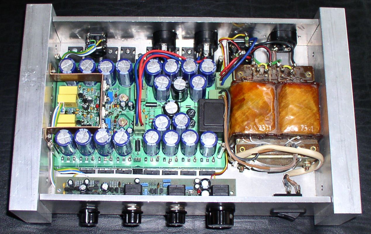
Also, at first glance, your PCB layout looks much better than the traditional ones with the power supply tracks on the sides, the small signal circuits in the middle, no ground plane, useless decoupling capacitors due to long PCB traces, and overlooked parasitic inductances everywhere.
I like your work, don't take them too serious. They enjoy heavy inefficient overbuilt amplifiers with $$$ exotic parts, while our tastes are probably the opposite (seeking something small, light weight, low cost, and still capable of doing the job properly from the electrical point of view).
Also, at first glance, your PCB layout looks much better than the traditional ones with the power supply tracks on the sides, the small signal circuits in the middle, no ground plane, useless decoupling capacitors due to long PCB traces, and overlooked parasitic inductances everywhere.
Last edited:
You can strong view it on superscription "M2K" and "Volume A, B".
There is no heavy cooler. And all your scheme is tricksy. I can only pressupose that it will explode by heat caused by performer transistors.
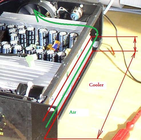
Below is a PCB cooler. Is cooled by a stream of air. The fan is on the rear panel.
I use 2sa1837 / 2sc4793 (much faster)
2sa1837 / 2sc4793 = 20W/70MHz
2SA968B / 2SC2238B = 25W/100MHz
Please do not measure THD at 1kHz, measure, please THD at 100kHz. Many transistors does a very slow amplifier.
I do not share your view that many transistor amplifiers inhibits SLR. THD is very important in all spectra of the transmitted band. Your amplifier is designed for hi-fi or just as universal? without demands for maximum fidelity recitation? Recommend to the simulation, a better measurement of THD. Shots are available from the scope screen?
Hey Federman
We are all striving for the same idea... Small, powerfull, reliable amplifiers that sound like angels. We are encouraging you to build the best amplifier that you can with the design you have in mind. The comments we give are those of experience. We also started in very much the same way you have. With a seemingly new idea, even in a similar thread.
We have been through the process of designing and building, and most importantly learning so much valuble information. We are in no way saying that your design is bad, we encourage everyone to try their designs, but we are offering a shortcut. You are more than welcom to go out and build the module with your specs, but I am very sure that you will be back here in this same frum, asking questions about "why my amp will not work"...
I would suggest that you do in fact build your amplifier in the way you suggest. Then during testing, try using some of the tips mentioned here. Make notes of the changes and which devices worked better etc. Once you have this information, then come and report back here. But you will find that what works on a pc being simulated, is VERY VERY different to what works in the real world.
There will be many people willing to help. This is how to approach the situation...
Step one : explain your idea and what you design goals are...
Step two : ask for other members opinions...
Step three : carefully consider all of the informaion...
Step four : Build the project...
Step five : do some basic tests...
Step six : Report back your findings to the members on the forum...
Step seven : spend the rest of your lifetime making modifications, and hopefully you might end up with your original design goals...
Good Luck mate
We have been through the process of designing and building, and most importantly learning so much valuble information. We are in no way saying that your design is bad, we encourage everyone to try their designs, but we are offering a shortcut. You are more than welcom to go out and build the module with your specs, but I am very sure that you will be back here in this same frum, asking questions about "why my amp will not work"...
I would suggest that you do in fact build your amplifier in the way you suggest. Then during testing, try using some of the tips mentioned here. Make notes of the changes and which devices worked better etc. Once you have this information, then come and report back here. But you will find that what works on a pc being simulated, is VERY VERY different to what works in the real world.
Are you looking for the real world. Everything is measured in the operating modules. I have devoted so many years of life.
Hi Federmann
I like your work, don't take them too serious. They enjoy heavy inefficient overbuilt amplifiers with $$$ exotic parts, while our tastes are probably the opposite (seeking something small, light weight, low cost, and still capable of doing the job properly from the electrical point of view).
Also, at first glance, your PCB layout looks much better than the traditional ones with the power supply tracks on the sides, the small signal circuits in the middle, no ground plane, useless decoupling capacitors due to long PCB traces, and overlooked parasitic inductances everywhere.
Hi Eva
I will add new photos soon.
Federmann, you display some strange ideas, that are potentially hazardeous and dangerous for potential less experienced builders. You have no working sample, how are EU safety norm applied? I must mention that, though I get a risk to be treated somehow. I hope there are some competent people who MUST see that.
I wasn't able to find the schematic of the PCBs shown on your posts. However, I found similar schematics.
Since you seem to be aimed towards rack-mount medium-power professional audio amplifier style, I think that a few things are missing on your circuits:
- Short circuit protection (current limiting for a few sec, then mute if overcurrent condition persists)
- Protection against too low load impedance (same as above)
- Protection against RF on the output (oscillation)
- Driver transistors between the VAS and the output stage if needed. They are probably not strictly required, but are likely to result in a reduction of THD and output impedance at high frequencies (often overlooked, but high output impedance above 1khz results in speaker dependent tonal imbalance).
- Current limiting on the VAS or driver transistors to prevent damage to the VAS and drivers in case something becomes open or shorted on output stage, or in case input signal demands a too high slew rate.
- Protection against overheating (maybe fan control too). Required when using small heatsinks and relying on the low duty cycle of music signals.
- Status
- This old topic is closed. If you want to reopen this topic, contact a moderator using the "Report Post" button.
- Home
- Amplifiers
- Solid State
- amp 1000W/2000W, IRFP240/9240