I am relatively new to the forums and apologize if this is not the right place to ask for help - I figured a DIY audio forum would be the best place to look for amplifier repair.
Anyway, I bought this amplifier two days ago - it worked perfectly when I first received it. After leaving the unit on over night with no music playing, I found the power indicator light to be "off". The receiver does not play audio now. If I turn the volume up all the way I do not hear any hum at all. I opened the case and cannot see anything burnt, fuse tested to have ~0 ohms resistance. When I power on the unit the relays fire, the transformer hums slightly (is energized). I really have no clue at all what it could be and it is driving me nuts.
This unit was actually purchased to replace another Sony receiver I had that "melted down" due to my own abuse. That unit similarly did not show any signs of burnt components or failed fuses. Maybe if I am lucky both of these can be fixed. What is peculiar to me is that this receiver failed with no load on it.
Could the transformers be going bad somehow?
Thank you!
One thing to check first is that both units are rated for your mains supply voltage... if they are adjustable are they set correctly ?
You really need a circuit...
however faultfinding at a very basic level means measuring the main rail voltages (across the big caps in the PSU) and seeing if the output devices are supplied with voltage (discrete or power IC ?)
A good clue has to be the power light... trace it back... what feeds it. Look for low voltage regulators... if the amp has remote control there will be a 5 volt rail... is there 5 volts on the remote receiver etc.
Transformers fail through overheating... very unlikely, and usually there is a thermal fuse buried in the primary winding. If it buzzes and fire the relay it's not that.
Pictures ?????
Thanks for the response! The amplifier is only rated for 120V which is the correct voltage, it is not adjustable.
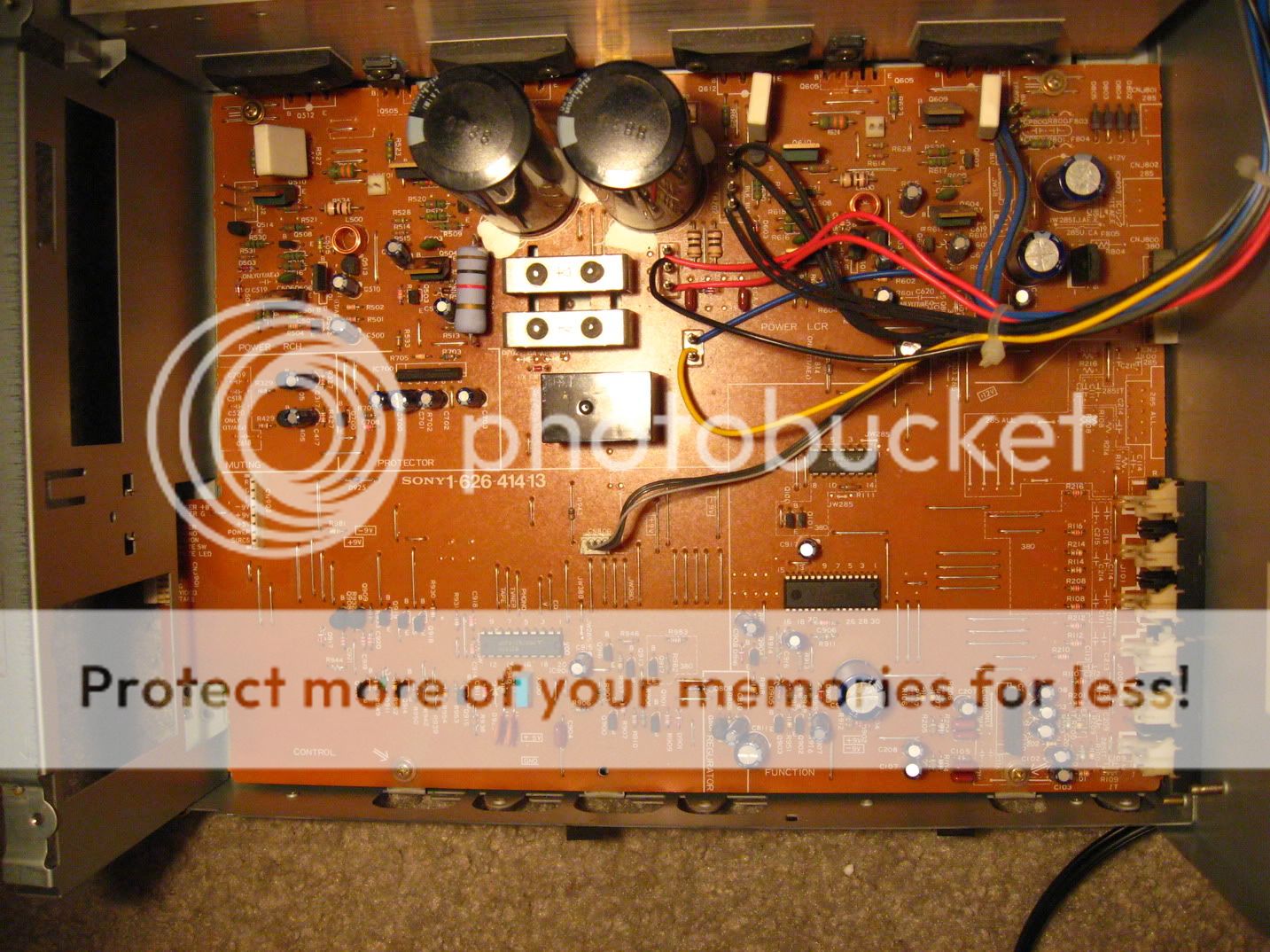
Where would these main rail/big caps in the PSU be... here is the main board below as well as the auxiliary board.
I will check what powers the light tomorrow morning. I notice that on the header to the front panel there is a +5v, +9v, and -9v marked. Maybe I should start there. I believe it is a discrete amplifier, how do I check?
Thank you!
Here are the direct picture links so you can read the circuit board...
http://img.photobucket.com/albums/v407/RudypooChris/IMG_1571.jpg
http://img.photobucket.com/albums/v407/RudypooChris/IMG_1566.jpg
This is a discrete amp as you can see 4 large power transistors (they probably have Sanken or SK written on em, right?).
The main filter capacitors are those two black cylinders at the top of the first picture. They could probably do with replacement, although that's a later job after you've found the first fault.
Checking if those 5v and 9v voltages are present is a good start. I'd lay good money that one of them isnt.
This is a discrete amp as you can see 4 large power transistors (they probably have Sanken or SK written on em, right?).
The main filter capacitors are those two black cylinders at the top of the first picture. They could probably do with replacement, although that's a later job after you've found the first fault.
Checking if those 5v and 9v voltages are present is a good start. I'd lay good money that one of them isnt.
Will check. Yes Sanken.
I have noticed now that the power indicator light glows ever so slightly - so it must be receiving some current. When the muting button is pressed, the light vanishes entirely. Just food for thought... probably very low voltage.
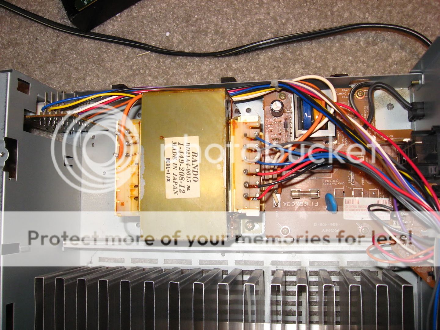
the specific amp features an stand by circuit ( see the small trafo next to the big one ) you need to carefully check how voltages a runing arround various circuits ( caution there is needed since there is dangeroius voltages related ) to find out if both of traffos are suplied
the click you may hear on start up might be the stand by relay but after that you need to listen to the click that comes from the protection relay
sorry to say that this cannot be trouble shooted by any one without any expirience ....
the click you may hear on start up might be the stand by relay but after that you need to listen to the click that comes from the protection relay
sorry to say that this cannot be trouble shooted by any one without any expirience ....
hmmm that is good then you should focus on the secondary power supply that give the 5 and 9 volt
a comon failure for this type of amps is the input selector IC
You are referring to the smaller transformer? I will trace back the 9v and 5v source tomorrow. Is that 5/9v source signal or is it something else that merely lets you know if power is running through specific stages?
Some good advice for you there Rudy.
Checking main supplies is always a good start.
Well just working from your pictures")
Is the relay that "clicks" the one next to the little transformer ? If it is you should have full mains voltage on the orange and white wires to the big transformer (AC remember to switch your meter)... those two on their own top left of tranny.
Theres a diode and small black cap next to that small tranny. What's the DC voltage on the strippy end of the diode.
Checking main supplies is always a good start.
Well just working from your pictures
Is the relay that "clicks" the one next to the little transformer ? If it is you should have full mains voltage on the orange and white wires to the big transformer (AC remember to switch your meter)... those two on their own top left of tranny.
Theres a diode and small black cap next to that small tranny. What's the DC voltage on the strippy end of the diode.
The low 5 volt rails are used to power the microprocessor etc and are a permanent supply. The big tranny is only powered when the amp is used... it's a way of saving energy and an easy way to implement a standby function.
The 9volt (is there a minus 9 ?) may only appear when the main tranny is powered.
The 9volt (is there a minus 9 ?) may only appear when the main tranny is powered.
Both the big one on the main board and the little one buried in wires on the "aux" board are clicking. I will check the AC volts and hopefully not fry myself during the process.
You say DC volts on striped end of diode is that striped end vs. chassis which I am assuming is grounded? Or striped end vs some other reference point?
There is a +9 and a -9. I see +5 but no -5... so I assume the 5v is merely for lighting and other things. I would suspect I have +5 but nothing on the 9v.
How does the amplifier know when to "standby". Every amplifier I have had, if you leave it "on" the large transformer stays warm, including this one. Thanks!
Last edited:
Chassis should be ground... all DC voltages for now are referenced here. For the AC supply obviously measure across the two wires.
It's one step at a time,
If the relay is OK and active, then mains will be present on the transformer. Next step is to check the secondary voltages are OK and present (we don't know the values)
What you can check... two quick tests.
With the amp unplugged measure on ohms across those white and orange wires. That's the primary winding and it will read very low, perhaps only an ohm or two... check it. If it's very high then a thermal fuse has "blown" . I think I can make that out in the picture, it will be those two off white wires going "into" the tranny primary. That should read zero ohms across those two.
The other check on ANY amp... just whack your meter on ohms and measure the output transistors... middle leg to the other two. Does it read short circuit on any ?
back on the right track ....first click on the auxiliary stand by board means that this board give voltage to the all amp ....second clic means that output stage is operational and measuring output tranistors is absolutelly not needed
now 5 volt is needed for the IC that does the logic stuff ... dispalys and memory of any kind +9-9 ( eventhough seems very low ) is needed for the rest of circuits such is preamp tone control and input selector IC to operate
this is te chain of things and you need all to operate too have a working amp
You mention the tranny stays warm in standby ? That doesn't sound right tbh by just looking at the pictures... and remember that's all I have to go on without a circuit.
I would say the mains supply should be switched to the large tranny via the relay... however lets not overlook anything.
Have you searched for a circuit ? it would be much easier
So the next step then is to power up the amp and measure on DC volts from chassis to the middle leg of the output transistors, (with apologies to Sakis but it really pays not to overlook anything)... and so there should be somewhere between 30 and 50 volts at a guess on two of them and minus 30 to 50 on the other two.
If that's OK the voltage on those four (I can only see 3, is one hiding ?) white resistors standing up near the outputs should be around zero volts on all connetions to them.
So far so good hopefully.
In your top picture, at the middle bottom of the board it says regulator. What's the voltage on the zener diode (ZD808 is it) and the transistor next to it. Whats on the 3 legs... be very careful, steady hands, a quick short of the leads from middle leg to the others could do serious damage.
Also top right of the board is what looks like an auxiliary supply... 4 diodes in a bridge. What's around there... the large cap/s it appears to feed.
Okay so here are my results.
Mooly:
I am getting 115VAC across the orange and white wires of the main tranny.
DC volts at striped end of diode to chassis ground ~11.65V but every 2 seconds or so it dids down to ~8.5v then returns to ~11.65v.
The output transistors read -62.1v, +62.1v, -62.1v, 62.1v. All four (yes one hiding) white resistors read 0VDC.
The diode "D808" reads 6.15v on striped end to chassis ground. Please clarify what measurement you would like me to make ont he 3 legs of the transistor - you are talking about the transistor labeled "Q801" with a "B" above it immidiately next to the words "REGULATOR" in the middle bottom of the top picture, correct?
After having the amp on with no signal to it for 10 minutes the main transformer is not warm, I guess it was staying warm earlier because I had devices attached to it, I don't know. I could not find a circuit.
Everyone:
My +9v reads ~9.375v which is fine, my -9V reads only -0.17v which is very not fine. +5V is at ~5.55v which also seems fine.
The front panel "power" indicator light runs off of the +9v and -9v circuits with a resistor inbetween (I assume to adjust the voltage down for the LEDs).
Sakis what is the input selector IC that you mention seems to fail frequently?
Attached is a picture of the top right of the main board... in the first picture of this thread the wires block the information here... it says -9V REGULATOR which may be of some concern now that I have determined the -9V circuit to be faulty.
http://img.photobucket.com/albums/v407/RudypooChris/IMG_1573.jpg
Thank you all for the continued support, I am just a poor college student. Can't really afford to replace the amp (plus I liked its sound), fortunately the person I bought it from gave me a full refund. If I can repair it I will send him the money back sans parts cost. =]
Check the transistor thats in the -9V regulator section. It's right next to a link marked -9V, and near the labelling R804. A quick easy check - power on, leave a minute or two, is that transistor warm/hot? If it's stone cold, odds on it's either toast, or the voltage feeding it is missing.
Jaycee, you would just love to have this on the bench to measure wouldn't you You can't beat working on discrete stuff like this.
So far so good... power stages seem OK... we had to check.
D808 reading sounds OK... I suspected this could be a 5 volt reference used to make a simple 5 volt supply with the transistor next to it... which would give around the 5.55 volts you measured (Diode less vbe drop)... so that seems OK.
So this -9 looks like the issue... has it just failed, or was it pushed by another problem/short etc.
Only one way to find out... can you tell us what the markings are on that "transistor" Jaycee mentions. To make a regulator from a transistor needs other parts... I don't see any (unless these is SMD underneath). Wondering if it's a regulator IC like a 7909.
Can you measure the voltages on all three legs ?
Also near the 4 diodes are what look like two "safety" resistors. With it turned off measure them on ohms... I would expect around 0.47ish to perhaps 4.7 ohms.
You can't beat working on discrete stuff like this.So far so good... power stages seem OK... we had to check.
D808 reading sounds OK... I suspected this could be a 5 volt reference used to make a simple 5 volt supply with the transistor next to it... which would give around the 5.55 volts you measured (Diode less vbe drop
)... so that seems OK.So this -9 looks like the issue... has it just failed, or was it pushed by another problem/short etc.
Only one way to find out... can you tell us what the markings are on that "transistor" Jaycee mentions. To make a regulator from a transistor needs other parts... I don't see any (unless these is SMD underneath). Wondering if it's a regulator IC like a 7909.
Can you measure the voltages on all three legs ?
Also near the 4 diodes are what look like two "safety" resistors. With it turned off measure them on ohms... I would expect around 0.47ish to perhaps 4.7 ohms.
Last edited:
- Status
- This old topic is closed. If you want to reopen this topic, contact a moderator using the "Report Post" button.
- Home
- Amplifiers
- Solid State
- Sony TA-AX380 Stopped Working