Somehow I cannot reach 55mv bias. It can be reduced to 230mv at minimum pot position. I used 1k multiturn trimpot.
Voltage across 100ohm resistors are 1.3vdc.
Other components are based on Greg's parts list.
Where should I look&check?
I mean, r21-r22. Parallel resistors with fuses.
Greg's build guide suggests removing fuses and check voltage between fuse clips for successful build.
'Connect your multimeter probes to the empty fuse clips F1 to read the voltage across the 100 ohm resistor R21.'
'Turn the power on while looking at your multimeter.
If the reading is more than 6V turn off immediately.
If the reading is in the 0.9V to 3V range then OK.'
Last edited:
I found my problem. I 'somehow' soldered 0.47ohm resistors between base-emitter pins of each output transistors..
What damage may cause this? Which parts should I change or replace?
Final note;
Don't drink while soldering!!
Most likely - no problem. Output transistors are closet this way. As soon as you correct the problem, the amp is going to run fine.
If there are no other mistakes
")
Cheets,
Valery

Member
Joined 2009
Paid Member
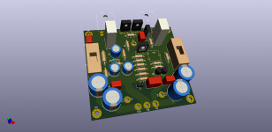
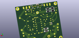
Made a layout for this little amp a while ago.
Still couldn´t fire it up due to other projects.
First layout after ages it seems so a few questionable choices like a mix of THT- and some SMD-parts.
First order at JLCPCB and I naively ordered a lot of 10 and will only need 4 max.
If anybody´s interested, I can let go of 6 PCBs for the cost of shipping.
Attachments
Sorry, only seen your message just now.I am looking for two PCBs from the Baby Aksa
If you can live with the few oddities my layout has, you sure can have two or more PCBs for shipping costs.
(I´m in germany)
Anybody tried to reduce the gain on the Baksa?
I´m sure I´ve read that you can reduce the gain on an Aksa at least some.
Otherwise I´ll go with a voltage divider at the input.
Thanks for the interest but Hugh ( Aksa ) found meSorry, only seen your message just now.
If you can live with the few oddities my layout has, you sure can have two or more PCBs for shipping costs.
(I´m in germany)
Anybody tried to reduce the gain on the Baksa?
I´m sure I´ve read that you can reduce the gain on an Aksa at least some.
Otherwise I´ll go with a voltage divider at the input.
two PCBs from the Aksa55 and the 100.
Thank you
You´re welcome and wow, that´s a good solution getting the original PCBs from the designer himself!Thanks for the interest but Hugh ( Aksa ) found me
two PCBs from the Aksa55 and the 100.
Get back when you have it working. I hope to fire mine up soon as well.
- Home
- Amplifiers
- Solid State
- Based on Hugh Dean's AKSA 55