Hello Hugh
It's hard find japanese numbers transistors here arround, I will look for a similar low cob high Ft low current US number transistor.
Is that was because of a better sound that you go back to single transistor VAS ?
I was using buffered VAS because that in simulations it was giving lower distortions, maby I should go back to single transistor VAS.
Thank
Bye
Gaetan
Last edited:
" . . . I've found the beta enhanced VAS (image C) harder to stabilise with low value cdom"
Why Gaeten? was it local parasitic issues as opposed to loop stability. I would think the beta enhanced CE VAS would be quite easy to stabilize. if you worry about the effect on bandwidth or SR, you can always up the LTP current.
Why Gaeten? was it local parasitic issues as opposed to loop stability. I would think the beta enhanced CE VAS would be quite easy to stabilize. if you worry about the effect on bandwidth or SR, you can always up the LTP current.
Gaetan,
I was wrong; should be MPSA18, not 15, my apologies.
With beta enhanced VAS you have two lag compensation choices; from emitter of buffer to VAS base, OR, from collect of VAS to VAS base. The former includes the buffer in the loop, which is is probably of little advantage since voltage gain of the buffer is unity and phase shift very small. But since the buffer output has very low impedance you'd better be sure the input stage can handle the charge slew for Cdom. The second, solely VAS comp technique is Self's preferred option, and it does result in lower values, I've verified this empirically.
For a VAS with active load and emitter to rail, gain set is maximum, and depends largely upon beta. Therefore loop gain is much increased with this configuration, and understandably compensation must pull this back to unity loop gain by the HF pole frequency. But if the VAS can now be run at lower currents, and thus higher impedances, a small Cdom should be fine, typically 30-40pF regardless of buffer current, seldom more.
Hugh
Last edited:
Hello
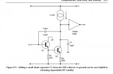
Looking at the 2009 edition of D. Self amp book, there is a beta enhance vas using a hf compensation cap (C1), any one have try that C1 with this type of vas ?
Btw, in his text Self suggested a quite big cdom cap of 100pf for the beta enhance vas, even without a phase lead cap, a 100pf cdom cap are much bigger than needed.
Here is the image of the beta enhance vas with hf compensation cap C1.
Thank
Bye
Gaetan
Attachments
Last edited:
comparing this to post27, I am confused.With beta enhanced VAS you have two lag compensation choices; from emitter of buffer to VAS base, OR, from collect of VAS to VAS base.
Is Q1 the buffer and Q2 the VAS? Q2 is the device sending output to the next stage and I have interpreted Q2 as the VAS.
Q1 buffers the VAS input.
But, could your description have swapped VAS to Q1 and Q2 is a buffer on the output? But Q2 cannot be a buffer it is a common emitter stage.
The pic above is the classic 'beta enhanced' VAS. Q1 is the 'buffer' and Q2 the VAS proper. Again, 'buffer' is not really what Q1 is - its there for beta enhancement to raise the VAS stage loop gain. I have looked at overall amplifer loop gain with and without beta enhancement in the VAS stage and the difference is about 12dB (simulated, but its quite accurate enough in this case) so Hugh's comments above are spot on in this regard. As to why DS seems to require 100pf, I cannot understand. I'm getting away with 33pf and 10mA tail current (yes, I like to run it HOT and fast !!). Then again, my LTP degen resistors are 150 Ohms, so loop gain is quite low.
Andrew,
Yes, I can see why, my bad......!
If Q1 is buffer, and Q2 VAS, then the two choices are collector of Q2 to base of Q2, OR, collector of Q2 to base of Q1.
Chris,
Self mentions 'constant gm LTP degeneration' in his early nineties papers, and this is clearly what you refer to. If you increase stage current in the LTP enough, you can add degeneration, in your case to straighten the normally S shaped transfer function, and keep gm of the first stage unchanged over low stage current, zero degen. This trick means that you keep the same loop gain, but you widen the linear operational region of the LTP, so that the error correction remains more accurate for a given loop gain. The additional loop gain you pick up using an EF to drive the VAS comes at little expense, possibly a bit of H2 and H3 because the EF is single ended, not much more, and thus reduces further the spray of artefacts beyond H4.
This is not so easy to follow, I haven't expressed it particularly well, but you get the idea. The weak point of the LTP is non-linearity of the LTP at high diff input - that is, high output from the amp - and this results in signal compression and odd order distortion.
My apologies,
Hugh
Last edited:
Hugh,
"The weak point of the LTP is non-linearity of the LTP at high diff input . . ."
that's why I like to run the LTP hot and use lots of degeneration. With 100 ohms and 5mA per side, you get a perfectly linear transfer curve up to circa 1V input - a la Leach (thank you Professor!)
"The weak point of the LTP is non-linearity of the LTP at high diff input . . ."
that's why I like to run the LTP hot and use lots of degeneration. With 100 ohms and 5mA per side, you get a perfectly linear transfer curve up to circa 1V input - a la Leach (thank you Professor!)
Can I guess that Leach thought along the same lines with 300r of degenaration in the LTP emitters?If you increase stage current in the LTP enough, you can add degeneration, in your case to straighten the normally S shaped transfer function, and keep gm of the first stage unchanged over low stage current, zero degen. This trick means that you keep the same loop gain, but you widen the linear operational region of the LTP, so that the error correction remains more accurate for a given loop gain.
For a VAS with active load and emitter to rail, gain set is maximum, and depends largely upon beta
I thought the gain of a CE stage was Rc/re where re was the VAS transistors internal emitter resistance and Rc is the external collector load, which for a CCS depends on the transistors early voltage (rc proportional to 1/VEarly) which is why the gain is so much higher han a resistive load that delivers the same bias current.
The weak point of the LTP is non-linearity of the LTP at high diff input . . ."
True, but the higher the loop gain the lower the diff input voltage (in a global feedback design) so LTP generation only works to a point (more degeneration= lower gain = higher diff input=more non-linearity vs more degeneration= a more linear diff input transfer function). Some where in there is an optimum LTP degeneration resistance.
The types of distortion and sound of this compromise is probably what really matters and I cant comment on that.
that's why I like to run the LTP hot and use lots of degeneration. With 100 ohms and 5mA per side, you get a perfectly linear transfer curve up to circa 1V input - a la Leach (thank you Professor!)
The input (across the + and - of the LTP) will only reach 1v (for an amp putting out 60v) if the loop gain is down to 60. Is this realistic?
Last edited:
I thought the gain of a CE stage was Rc/re where re was the VAS transistors internal emitter resistance and Rc is the external collector load, which for a CCS depends on the transistors early voltage (rc proportional to 1/VEarly) which is why the gain is so much higher han a resistive load that delivers the same bias current.
Yes, but if for example we use a perfect CCS, a fictitious beast, with Z of say 2M. If the VAS runs at 6.5mA, re is 26/6.5 = 4R, and theoretical gain of this common emitter amplifier is 2exp6/4 = 500,000 or 114dB. I have never seen an OLG of 114dB on a conventional single stage VAS audio amplifier, typically loop gain is about 65dB max, which with CLG of 30dB indicates 95dB of OLG.
So clearly OLG does not approach the calculated limits. Something is holding it back. That something is die geometry, and particularly beta.
True, but the higher the loop gain the lower the diff input voltage (in a global feedback design) so LTP generation only works to a point (more degeneration= lower gain = higher diff input=more non-linearity vs more degeneration= a more linear diff input transfer function). Some where in there is an optimum LTP degeneration resistance.
Yes, exactly. We are saying the same thing. This is an artful compromise.
The types of distortion and sound of this compromise is probably what really matters and I cant comment on that.
Perhaps that could be your next quest.... there is precious little correlation between the intoxicating engineering and the subjective results.
The input (across the + and - of the LTP) will only reach 1v (for an amp putting out 60v) if the loop gain is down to 60. Is this realistic?
Are you sure about this? I believe it is the output of the amp divided by the loop gain, which means for 60Vp output (225W into 8R) and moderate loop gain of 60dB, this is 120mVpp differential voltage across the + and - inputs of the LTP. If you had 1V diff input across the LTP both transistors would go into alternate hard saturation and square wave output would result.
Cheers,
Hugh
Last edited:
Yes, but if for example we use a perfect CCS, a fictitious beast, with Z of say 2M.
Its the early voltage of the CCs I refer to not a perfect CCs.
Are you sure about this? I believe it is the output of the amp divided by the loop gain, which means for 60Vp output (225W into 8R) and moderate loop gain of 60dB, this is 120mVpp differential voltage across the + and - inputs of the LTP. If you had 1V diff input across the LTP both transistors would go into alternate hard saturation and square wave output would result.
I think you misunderstood me. We are saying the same thing. Bonzai says his LTP is linear to a 1 volt input, and I was trying to say that its unnecessary to go that high, that he dosnt need that much degeneration, because any GFB design has enough gain to limit the input neccesary to max the output.
"The input (across the + and - of the LTP) will only reach 1v (for an amp putting out 60v) if the loop gain is down to 60. Is this realistic? "
I am talking about the diff pair in isolation, before closing it within a GNF loop. You need wide differential linearity of the front end to be able to cater for the maximum input signal. When the loop is closed and the amp input is excited with a fast rise time signal, Vi-Vf must remain linear. If this is not the case, you get distortion (since Vi-Vf would not be a linear function), and under worst case conditions (low differention linearity, heavy Cdom, low LTP tail current) it can lead to TIM. An input filter is also important to control the rise times, although DS does not seem to put much store in this.
Leach has a nice explanation in his Leach amplifier page - see the front end diff amp discussion. DS also shows some graphs in his 'Audio Power Amplifer Design Handbook' dealing with this.
" ...Bonzai says his LTP is linear to a 1 volt input, and I was trying to say that its unnecessary to go that high, that he dosnt need that much degeneration, because any GFB design has enough gain to limit the input neccesary to max the output. "
At DC yes - you are absolutely correct. But, music is not DC - you need to think about a dynamic music signal.
At DC yes - you are absolutely correct. But, music is not DC - you need to think about a dynamic music signal.
because any GFB design has enough gain to limit the input neccesary to max the output. "
At DC yes - you are absolutely correct. But, music is not DC - you need to think about a dynamic music signal.
This is very true & worth notice
")
All transistors has got one gain at DC and another gain at any AC frequency.
If they had only one HFE gain, the gain at DC, it would be very easy to make perfect amplifiers.
But already at 1 kHz an amplifier can have maybe only 50% gain left. Compared to DC.
Now, consider sound signals up to 10-20 kHz,
and we can see things are not at all as our calculated DC gain, HFE.
A good designer will calculate for these losses and try to use an estimated lower AC gain figure.
An approach I often use, is to use a gain figure round 50% of the DC HFE.
This way I make sure there is enough gain, overall, at higher frequencies.
- Status
- This old topic is closed. If you want to reopen this topic, contact a moderator using the "Report Post" button.
- Home
- Amplifiers
- Solid State
- What are the pros and the cons of those 3 vas ?