Hi
Some of my ........................
")
The beta enhanced has a much higher input Z and your input stage likes this very much but it adds another stage within the closed loop. The buffered VAS allows you to use a small signal transistor for the VAS which tends to have better gain linearity and higher GBW. The cascode VAS requires extra voltage for the supply rails in order to get around the lost cascode voltage. However cascode has wonderful benefits. For starters it allows you to use a lower Vce small signal device for the current amplifier and this brings out all kinds of possible components. Lower Vce transistors tend to have higher Hfe, much faster GBW and lower noise, and it does not add an extra stage in the CL. Also having a constant Vce not only will linearize the AC load line, it inhibits the Early effect. There are also benefits to having the voltage amplifier being common base instead of common emitter. Certainly as far a quality is concerned, cascode is the best way to go for sure, but like I said, it needs a boosted supply voltage to get rail to rail swing at the output stage and this adds complexity to the overall circuit. There are always trade-offs.
As for my amp, I use a voltage doubling circuit that then looses several volts in a series-shunt voltage regulator for the low current VAS and input stage supply placing it about 10V greater than the output stage rail. It's not a terrible addition to complexity but is well worth the benefits.
Some of my
........................The beta enhanced has a much higher input Z and your input stage likes this very much
but it adds another stage within the closed loop. The buffered VAS allows you to use a small signal transistor for the VAS which tends to have better gain linearity and higher GBW. The cascode VAS requires extra voltage for the supply rails in order to get around the lost cascode voltage. However cascode has wonderful benefits. For starters it allows you to use a lower Vce small signal device for the current amplifier and this brings out all kinds of possible components. Lower Vce transistors tend to have higher Hfe, much faster GBW and lower noise, and it does not add an extra stage in the CL. Also having a constant Vce not only will linearize the AC load line, it inhibits the Early effect. There are also benefits to having the voltage amplifier being common base instead of common emitter. Certainly as far a quality is concerned, cascode is the best way to go for sure, but like I said, it needs a boosted supply voltage to get rail to rail swing at the output stage and this adds complexity to the overall circuit. There are always trade-offs.As for my amp, I use a voltage doubling circuit that then looses several volts in a series-shunt voltage regulator for the low current VAS and input stage supply placing it about 10V greater than the output stage rail. It's not a terrible addition to complexity but is well worth the benefits.
Last edited:
Member
Joined 2009
Paid Member
Member
Joined 2009
Paid Member
If the amplifying transistor has Vce of 5V and a med pwr device is used for the cascode transistor, 40-50mA bias could be used. Do you need a VAS with more current than that? A small signal TO-92, even with Vceo less than 25V could easily be the current amplifying transistor, perhaps with Hfe greater than 300. This would negate the need for the extra current gain stage and still only require ~150uA of DC bias from the input stage. You could even use J-fets.
 The biggest issue is the extra boosted voltage supply required to make up the cascode voltage difference. This may be the reason to go with one of the other solutions but cascode really is hard to beat in terms of performance.
A small signal TO-92, even with Vceo less than 25V could easily be the current amplifying transistor, perhaps with Hfe greater than 300. This would negate the need for the extra current gain stage and still only require ~150uA of DC bias from the input stage. You could even use J-fets. The biggest issue is the extra boosted voltage supply required to make up the cascode voltage difference. This may be the reason to go with one of the other solutions but cascode really is hard to beat in terms of performance.
Last edited:
Hello
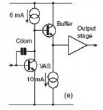
There is also the VAS with a collector buffering, like in the image.
I never try this one, do we connect the collector of the buffer transistor to the upper rail ?
Anyone did try this one, any amps who use this VAS ?
Thank
Bye
Gaetan
There is also the VAS with a collector buffering, like in the image.
I never try this one, do we connect the collector of the buffer transistor to the upper rail ?
Anyone did try this one, any amps who use this VAS ?
Thank
Bye
Gaetan
Attachments
Hello
Wich one are better between the VAS E (buffering VAS collector...) and F (the bootstraping VAS load R) in the image I include ?
I've try the VAS E (buffering VAS collector...) in simulation, but connecting the collector of the buffer transistor to the upper rail did not work correctly.
For now I mostly use the VAS F (the bootstraping VAS load R), and I just found out today, in simulation, that raising the 220 ohm R up to 8K ohm reduce the gain and the distortion of the VAS and amps.
Thank
Bye
Gaetan
Attachments
Last edited:
By CBS240- However cascode has wonderful benefits. For starters it allows you to use a lower Vce small signal device for the current amplifier and this brings out all kinds of possible components. Lower Vce transistors tend to have higher Hfe, much faster GBW and lower noise, and it does not add an extra stage in the CL.
This all translates to better sound. Sort of a blend between the beautiful mids and highs of the symasym and the tight bass of a fully complimentary design.
you can "dial in" as much early effect as you want with a "magic resistor" between the current amp and cascode. As far as rail loss , try to set your cascode voltages to 2V minimum under rails (green/blue led) , I have even seen double diode setups (luxman).
By andrew T. If Cascode is adopted, it must drive a high impedance load, either a buffer or a 3stage output.
My GX has no problem with a standard EF2 , all the way up to 120v P/P with a 4R load (transient only). I run a 5ma VAS . Who would need 40ma+ ?? Being more complicated and taking up space ...?? With correct layout, the current amps and cascodes are "back to back" on the same heatsink taking up no more space than a "blameless" , you might need a couple sq. CM's to add your zeners/led's ... not a real issue.
OS
This all translates to better sound. Sort of a blend between the beautiful mids and highs of the symasym and the tight bass of a fully complimentary design.
you can "dial in" as much early effect as you want with a "magic resistor" between the current amp and cascode. As far as rail loss , try to set your cascode voltages to 2V minimum under rails (green/blue led) , I have even seen double diode setups (luxman).
For me, I try to avoid any Early effect if possible.
Keeping less than 8-10V across the current amp transistor should prevent this, but cascode effectivly straightens the Ic vs Ib relationship. Even for the low Vce HF devices, Early voltage is usually higher than 8V. With 10-12V above the power rail, one could leave Vce of 6-7V on the current amp and set the cascode voltage to a few volts above the max Vin for the output follower, and use a clamp + resistor so as not to cause the VAS current amp transistor or the driver to saturate at clipping.Pete,
The issue with the cascode is the very high Zout; this means that variations in input impedance of the output stage will have profound influence on the voltage output.
I favor the buffered VAS; this has the advantage of greatly reducing VAS to 1 or 2 mA, and the buffer then gives very low Zout, around 2.5R for 10mA, which will easily power through any impedance variations in the drive to the output stage.
All these approaches can work very well in terms of sound quality. I have found the magic resistor (cf. Peufeu) best with a 200mV drop, and have made cascodes work well in the past. But I keep coming back to the very high Zout, which of course is also a problem for the single, unbuffered VAS.
Another one to consider is the CFP VAS. These can work very well too.
Hugh
Hi,
Gaetan's thumbnails :
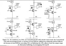
In "e" the 220 Ohm resistor is bootstrapped by the emitter follower, itself loaded by a CCS : the 220 Ohm presents a high load to the VAS.
In "f", the VAS is loaded by a first CCS and followed by an emitter follower conventionnaly loaded by a second CCS. So "f", with its two CCS's, has more components than "e".
Some time ago, there was a question about the difference of quality between "e" and "f", and there was no response.
According to Self, "e" is more distorting than "f" :
Discrete design: More on 2-transistor shunt-feedback amplifiers
Having used a bootstrapped resistor in the VAS of his Mosfet amplifiers, Mike Renardson found that, for ultimate performance, this resistor should be replaced with a CCS, which, in fact, turns out to be a bootstrapped CCS. Its implementation needs a bit more of voltage drop than the 0.6 V across the previous resistor :
MJR9
Some simulations tend to show that the circuit of a VAS loaded by a bootstrapped CCS itself loaded by a second CCS (like in Renardson's scheme) gives slightly lower distorsion than "f". This is quite normal as its first CCS
has almost constant voltage across it. It may also have a superior PSRR.
Gaetan's thumbnails :
In "e" the 220 Ohm resistor is bootstrapped by the emitter follower, itself loaded by a CCS : the 220 Ohm presents a high load to the VAS.
In "f", the VAS is loaded by a first CCS and followed by an emitter follower conventionnaly loaded by a second CCS. So "f", with its two CCS's, has more components than "e".
Some time ago, there was a question about the difference of quality between "e" and "f", and there was no response.
According to Self, "e" is more distorting than "f" :
Discrete design: More on 2-transistor shunt-feedback amplifiers
Having used a bootstrapped resistor in the VAS of his Mosfet amplifiers, Mike Renardson found that, for ultimate performance, this resistor should be replaced with a CCS, which, in fact, turns out to be a bootstrapped CCS. Its implementation needs a bit more of voltage drop than the 0.6 V across the previous resistor :
MJR9
Some simulations tend to show that the circuit of a VAS loaded by a bootstrapped CCS itself loaded by a second CCS (like in Renardson's scheme) gives slightly lower distorsion than "f". This is quite normal as its first CCS
has almost constant voltage across it. It may also have a superior PSRR.
I've tried both.
1. A 'buffered' VAS (C from Self above) simply gives better VAS linearity because the extra small signal transistors raises the VAS loop gain enclosed within Cdom. The correct name for this is a 'beta enhanced' CE VAS stage. Simple and works well on fully complementary designs with resistive LTP loading as well.
2. Cascode ('d' in Self Above). I have an amp running with this - fully complementary design. Zo is high, but the trick it to feed the VAS into a triple EF output stage. Re the 'magic resistor' you can also use this resistor as a current limiter for the VAS when the output stage current limiting kicks in.
3. Others - have'nt tried them, but my next power amp will use a Hawksford cascode.
Last edited:
Hello
I did try other VAS, I've found the beta enhanced VAS (image C) harder to stabilise with low value cdom capacitor, and the VAS buffered collector (image E) was not work as I expected.
So I've go back to the bootstraping VAS load R (image F) , but rainsing too much the value of R (the 220 ohm resistor) cut the current to the VAS transistor collector and cut a lot the bandwith of the KSC3503 VAS transistor. A resistor R of 220 ohm are quite right since the VAS transistor and the buffer transistor will have quite same current but maby the buffer one need more current than the VAS one.
Bye
Gaetan
Attachments
Last edited:
Hello
Here is one of my amp using the bootstraping VAS load R (image F), a standard Lin topology with matched LTP transistors and phase lead cap, etc.. It sound very good.
I'm not sure, but is the buffer transistor should need more current than the VAS transistor ?
In this amp schematic the VAS transistor have 3 ma and the buffer transistor have 4 ma.
Bye
Gaetan
Attachments
Last edited:

One advantage as I can see for a normal Darlington instead of Q7/Q5 Sziklai
is that the first transistor, Q7, can have a constant collector voltage.
That is when collector is connected to Ground or even V+
(Most common is Ground, like e.g. Self does in Blameless)
Constant collector voltage can be achieved evenso when using Sziklai, like in Gaetan's schema.
We can cascode Sziklai. Either cascode only Q7 or put both transistors inside the cascode.
I do not know eventual benefit in Gaetans VAS,
but I have cascoded Sziklai sometimes with very good simulation results.
Other times there were no benefits, or even made things worse.
- Status
- This old topic is closed. If you want to reopen this topic, contact a moderator using the "Report Post" button.
- Home
- Amplifiers
- Solid State
- What are the pros and the cons of those 3 vas ?