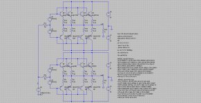
I am running simulation to evaluate distortion structure of a push-pull emitter follower stage. It has four-pair devices in parallel. In order to simulate unmatched pairs, I have one circuit having different NPN devices: NJL3281, MJL21194, MJE340 and 2N2055. All PNP are NJL1302. Simulation results show that perfectly matched output THD is slightly higher than that of unmatched output. On the other hand, unmatched output has more energy locating at higher order harmonics.
Vbe of different NPN is slightly difference. Hence, we have cross-over distortion of each NPN/PNP arm difference slightly. Will it lead to some sort of cancellation?
Real circuit shows similar results?
Figures: LTspice schematic and FFT of V(out1) matched, V(out2) unmatched.
Vbe of different NPN is slightly difference. Hence, we have cross-over distortion of each NPN/PNP arm difference slightly. Will it lead to some sort of cancellation?
Real circuit shows similar results?
Figures: LTspice schematic and FFT of V(out1) matched, V(out2) unmatched.
Attachments

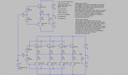
This simulation compares single-pair output to four-pair output. There are two cases for the four-pair output: all identical NPN and unmatched NPN as in the previous example.
Single-pair THD = 0.133%
Four-pair (matched) THD = 0.115%
Four-pair (unmatched) THD = 0.0264%
Does the result make sense?
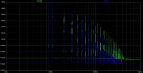
Spice schematic is shown in the picture. FFT shows single-pair and unmatched four-pair output.
Single-pair THD = 0.133%
Four-pair (matched) THD = 0.115%
Four-pair (unmatched) THD = 0.0264%
Does the result make sense?
Spice schematic is shown in the picture. FFT shows single-pair and unmatched four-pair output.
Attachments
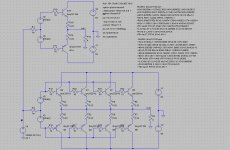
Base stopper resistors are added to the above circuit. One simulation is for all base resistors equal to 10 R. One simulation is for different stopper values for the four NPNs. All NPN/PNP are identical (perfectly matched).
single-pair, 10 R stopper: THD (4R) = 0.66 %, THD (8R) = 0.262 %
four-pair, 10 R stopper: THD (4R) = 0.236 %, THD (8R) = 0.131 %
four-pair, 10R, 15R, 20R, 12R stopper for NPNs: THD (4R) = 0.2033%, THD (8R) = 0.118 %
Different stopper value cause each NPN passing different bias current.
Is it a valid method to simulate unmatched pairs? Does the simulation make sense? Does matching not improve but degrade overall linearity?!!!
Attachments
Yes, and different output current sharing.Different stopper value cause each NPN passing different bias current.
The stopper subtracts Vrs from Vbe multiplier and the remainder is applied as output Vbe. a very small change in output Vbe will give rise to very different current sharing.
I match base stoppers and match emitter resistors as well as match output devices. Other wise there would be no point in doing any matching.
That's why I want to see discussion of your sim predictions.
base stopper, if fitted, and Re <=0.5%
I clamp the two outputs together with a strip of aluminium between.
join the bases and apply a Vbe until Ic matches the operational current. This only sets the Vbe to Ic match.
You also need an hFE match at operating Ic.
This time you add a pair of base stoppers and apply the V through them to turn on the output devices. Compare voltage across the base stoppers to find hFE matches.
You can do these tests in either order after rough sorting into similar parameter groups.
I tend to do the base stopper resistor measurements first. When I have pairs that look as likely matches I short out the stoppers and adjust the Ic back down to operating IC.
Using a 317 as CCS set to 2times operating current does this adjustment automatically.
The next stage would be to alter the 317 CCS current and see if your selected pair match over a range of operating currents. This would be equivalent to using a curve tracer. I do not do this Ic sweep with output devices. I reserve this level of matching to LTPs only.
Last edited:
Honestly, I think your findings do not make much sense. There is no distortion cancellation mechanism at work that somehow does not work for matched pairs. It's a pity I can't have a closer look at this right now to help you find the cause.
Matching in output pairs is only done to ensure all devices reliably turn on and as VBE variations are tiny compared to VGS of mosfets, it's commonly done only for mosfets.
For current sharing, the usual degeneration does the job.
All the best, Hannes
Matching in output pairs is only done to ensure all devices reliably turn on and as VBE variations are tiny compared to VGS of mosfets, it's commonly done only for mosfets.
For current sharing, the usual degeneration does the job.
All the best, Hannes
Thank you Hannes.
Since degeneration resistor is employed, can I simply skip matching for bipolar?
You can in the case of bipolar as the Vbe's are usually very close anyway.
I suspect a lot of the nastys associated with unmatched transistors expected are got rid of by feedback and emitter/source resistors.
I have built numerous amps and never bothered matching MOSFET's and they have all worked and sounded fine.
I tend to agree your opinion. It seems matching not making sense for output devices. It may be just for selling higher prices.
Do you think matched (or selected) output devices contribute to better performance, e.g. THD?
Without global NFB matching is more or less needed.
Vbe vs Ic (or Vgs vs Id) operational are matched to help ensure current sharing.
If both devices pass the same current and both are at the same Vce/Vds then both dissipate the same heat.
If both are equally cooled then both junctions will be at the same temperature.
If both pass a high current transient, the the rate of instantaneous heating will be the same and the peak Tj will be the same.
This is what Bob means by "matching improves reliability".
Conversely,
if they are not matched then unequal Ic will ensure that the Tc and Tj before the transient comes along are different and when the transient does appear there is no way to ensure that the rate of instantaneous heating will be the same. One device is guaranteed to run hotter than the average.
I roughly matched Lfets and replaced the wrong devices in a 2pair power amp. There was terrible Ibias matching. One was running ~30% more current than the next highest.
I then matched the Re. I bought and matched 16pr to set up enough for 4off 4pr output stages. I used the worst quads for the first rebuild. 7 FETs were very close to matched and the 8th was about 5% collector current in error (at the same Vgs). Once installed that 8th became a 10% more current than the next highest. But since I now had 4pr replacing 2pair I settled for the extra margin that was built in. This was quite a few years ago so my memory will have jumbled some of the data, but the message was clear for equal operating temperatures matching is mandatory.
If equal operating temperatures are of little or no importance to you, then matching is irrelevant.
BTW,
BJTs are just as bad. the increased transconductance requires very close matching of Vbe. If both devices have identical Vbe (connected together) and both devices have identical Tc (clamped together) then measure the Ic through each.
Since both Vbe iare fed from the same low source impedance, differences in hFE are completely eliminated from this test.
Last edited:
Vbe vs Ic (or Vgs vs Id) operational are matched to help ensure current sharing.
If both devices pass the same current and both are at the same Vce/Vds then both dissipate the same heat.
If both are equally cooled then both junctions will be at the same temperature.
If both pass a high current transient, the the rate of instantaneous heating will be the same and the peak Tj will be the same.
This is what Bob means by "matching improves reliability".
Conversely,
if they are not matched then unequal Ic will ensure that the Tc and Tj before the transient comes along are different and when the transient does appear there is no way to ensure that the rate of instantaneous heating will be the same. One device is guaranteed to run hotter than the average.
I roughly matched Lfets and replaced the wrong devices in a 2pair power amp. There was terrible Ibias matching. One was running ~30% more current than the next highest.
I then matched the Re. I bought and matched 16pr to set up enough for 4off 4pr output stages. I used the worst quads for the first rebuild. 7 FETs were very close to matched and the 8th was about 5% collector current in error (at the same Vgs). Once installed that 8th became a 10% more current than the next highest. But since I now had 4pr replacing 2pair I settled for the extra margin that was built in. This was quite a few years ago so my memory will have jumbled some of the data, but the message was clear for equal operating temperatures matching is mandatory.
If equal operating temperatures are of little or no importance to you, then matching is irrelevant.
BTW,
BJTs are just as bad. the increased transconductance requires very close matching of Vbe. If both devices have identical Vbe (connected together) and both devices have identical Tc (clamped together) then measure the Ic through each.
Since both Vbe iare fed from the same low source impedance, differences in hFE are completely eliminated from this test.
Hi Andrew how does Hfe effect matching of push pulls.I was attempting to fix my NAD3020 output stages of 2n3055/Mj2955.I find the current replacements have huge Hfe variations from as low as 30 to 190...will this effect the performance ,could i get the intended sound quality?
Thanks in advance
- Status
- This old topic is closed. If you want to reopen this topic, contact a moderator using the "Report Post" button.
- Home
- Amplifiers
- Solid State
- Parallel output with/without matched devices