sam9 said:
A simple example" in a a project I have under way for a modest powered amp one problem is that my first version exhibited significant "rail-sticking" with the probable result that it would sound horrendus when clipping or near clipping (an important consideration when modest power levels are involved). The solution turned out to be replacing the beta-enhanced VAS with someting less agressive.
There's always the Baker clamp trick too (see below). There's a slight increase in distortion from this, but it allows for a beta-enhanced VAS, which pretty much makes up for it.
Attachments
I have seen the Ben Duncan book from my library, they had to order it though from afar....its ok, a useful addition to the idiom, but there are still things I would like to see that it doesn't have in.
It assumes a lot, I suppose its true to say that most of these books are written by engineers for engineers, and this is no exception, its not a nice lucid read as such. Most of these lot don't write that well. But it may be what you are seeking. Pricy, yes. Check out amazon s/h to see if you can get it cheaper.
I think the best chapter is the one on topologies.
John Linsley Hood is ok, too, but again its a bit 'bitty' and no real logical progression. Duncan is more ordered in that sense, still far from perfect. Slone and Self go furthest in that respect, I do feel Slone gets a little repetetive at times.
For Valves,Morgan Jones is superb, followed by Rozenblit.
Steven, thanks for posting that. When I'm at work I can't post - too much going on! So I appreciate your jumping in and providing the very clear illustration.
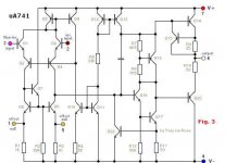
Sam, since I'm no longer at work I can provide more detail. In the two circled areas, the diodes oriented horizontally are normally OFF and the vertical ones are normally ON. For the lower vertical diode, it's biased at about 3 mA by the collector current of the VAS input buffer. It's kind of hard to see, but this collector does not connect to the emitter of the common base amp (IOW there's no dot there). The upper vertical diode is biased at 3 mA by the PNP current source. On the negative half cycle at clipping, the lower horizontal diode turns ON. If we assume the voltage drops across the lower horizontal and vertical diodes are equal in this state, the collector-base voltage of the NPN common base amp will be zero. For a transistor to be saturated, its collector-base junction must be forward biased. So the clamp just barely keeps the device out of saturation while only reducing the voltage swing by a few tenths of a Volt. The NPN emitter follower that connects to the lower diodes provides a fairly low impedance to the base of the NPN common base amp, and will also drive as much current as necessary to the diodes during clipping so as to keep the base voltage of the common base amp from "bouncing". If it weren't there, and the junction of the two diodes were connected directly to the TL431 voltage reference instead, the increased current from the horizontal diode when it turns ON would be enough to turn off the TL431 by starving it of DC current. So this emitter follower sourcing the current of the Baker clamp helps provide a very clean constant output voltage when clipping. A similar effect happens with the upper Baker clamp diodes and PNP emitter follower on the positive half cycle.
To demonstrate the Baker clamp in simulation, it's helpful to just use ideal DC voltage and current sources for biasing as necessary, to keep things simple. Without the Baker clamp, you can observe the amplifier output voltage and the base current of the main VAS transistor when clipping occurs. When the amplifier clips, you'll see a big increase in the base current of the VAS transistor, up to a few mA or more due to saturation. With real-world bias circuits using zeners or voltage references, this large base current is sometimes enough to turn off these voltage references, as they may only be biased to a couple of mA themselves. When you put in the Baker clamp and observe the base current of the VAS transistor during clipping, you'll see that the base current does not increase much. There may be a few short spikes due to capacitive effects, but not the large increase in base current that happens in saturation for the duration of the clipped portion of the output voltage. This shows that saturation is effectively prevented by the Baker clamp. I don't know if this is true in real life, but the SPICE model of the MJE340 shows that it takes about 1 us to get it out of saturation. So if it's allowed to saturate, it will "stick" at the rail for an extra 1 us when it should be recovering. Strangely, the MJE350 model doesn't seem to do this. Maybe I'll try to post some pictures of this over this weekend.
Another example of the Baker clamp in an amplifier is the original '70s Ampzilla design by Bongiorno, whose schematic is shown here http://home.kimo.com.tw/skychutw/ampzilla/Ampzilla.htm. If the diode drop is the same as the Vbe of the VAS input follower, the Vcb of the VAS common emitter amp will also be clamped at zero during clipping, thus preventing saturation. Bascom H. King reviewed this amp in Audio about thirty years ago, and remarked at how "sticking" was completely absent. The Baker clamp is what makes this happen.
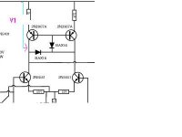
Here's some pictures of the instantaneous base current of the NPN common base transistor of the VAS when clipping occurs. Since the device names in the original picture of the circuit aren't readable, I've posted a closeup of the part of the circuitry I'm looking at below. First, I removed D2 to disable the Baker clamp. Then I looked at the base current of Q10 vs time during clipping. Some interesting things happen.
Attachments
You can see that when Q10 saturates on the negative half cycle of clipping, the base current goes way up. Q14 is sourcing about 50 mA to the base of Q10 in this condition. Another interesting thing occurs when recovering from clipping. To pull Q10 out of saturation requires pulling the stored charge out of its base, resulting in a negative base current of about 3 mA for about 4 us (not 1 us as I erroneously stated in a previous post). Why 3 mA? That's the bias current of Q14, provided by the collector of Q13. So what happens is that Q14 goes into cutoff in this condition, and D1 turns OFF. Then Q13 ends up sinking all the negative base current of Q10. Since Q14 is in cutoff and D1 is OFF, we have essentially lost control of the base voltage of Q10 in this state. This will result in rather poor recovery from clipping.
Attachments
Then I put D2 back to look at the same situation with the Baker clamp present. You can see that the behavior in clipping is much more civilized. The base current of Q10 is only a few mA, and since saturation is avoided, there's no negative base current in Q10 at any time.
This brings up several observations. In a cascoded VAS, if the common base amp is allowed to saturate during clipping (the normal case), getting the best possible recovery from clipping requires buffering the voltage reference that provides its base bias voltage. Further, this buffer must be able to source and sink significant amounts of current. A simple emitter follower will go into cutoff as the feedback action of the amp tries to bring Q10 out of saturation.
However, if a Baker clamp is used, the requirement on the buffer for the base bias voltage is actually less severe. It mostly provides current in only one direction, so a simple emitter follower can be used. It still must provide significant current to D2 during clipping though, but that is all in the "good" direction of the emitter follower.
Attachments
Another option for Baker clamp
Another option for the Baker clamp, as I used it 20 years ago, is using a Germanium diode for D2. In that case you can leave out D1 (becomes a short). The voltage drop of a Ge-diode is small enough to keep Q10 from saturating. I used AA117 diodes. These are 115V, 50mA max. I noticed these are still for sale. It is also possible to use a Schottky diode for D2 and leave out D1. But be careful with the maximum reverse voltage. Schottky diodes are a little limited in that respect.
I'm not sure, however, whether the name "Baker clamp" is still valid for this case. More important is that it works.
Steven
I also tried two diodes in series for D1 and looked at the Q10 base current. With a single diode for D1, the base current peaked out at about 2 mA, and with two diodes for D1 it peaked at about 1.7 mA. Then I realized that the Q10 collector current is going up to about 55 mA at clipping, which is rather large. I may limit the collector current of Q10 to about 30 mA or so by having a current limiter that shunts the base drive away from Q13.
Hi thanh,
As far as I remember, R2 in your 741 circuit is just there to increase the current through Q7 to improve high frequency behaviour. There is no straightforward way to calculate the right value, since it depends heavily on the transistor characteristics.
Since the base current of Q7 is small anyway, it will hardly affect the accuracy of the current mirror Q5+Q6, so the value of R2 is not critical. I think the 741 uses a buried resistor for R2 because of the high value, which is very inaccurate (50% tolerance).
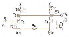
You should NOT use R12 in panzerlord's circuit. It will spoil the accuracy of the mirror Q1+Q4 and because of that of the whole Wilson mirror Q2+Q24+Q1+Q4. Base current of Q1 and Q4 is coming from the left leg of the mirror via the collector-base connection of Q4. Adding R12 would increase that current, causing an unbalance. Replacing the collector-base connection by a transistor, like Q7 in the 741, would allow for putting R12 there, but even then the performance will be worse. The Wilson current mirror uses base current cancellation, which is ruined by the addition of a kind of Q7 and R12.
Steven
As far as I remember, R2 in your 741 circuit is just there to increase the current through Q7 to improve high frequency behaviour. There is no straightforward way to calculate the right value, since it depends heavily on the transistor characteristics.
Since the base current of Q7 is small anyway, it will hardly affect the accuracy of the current mirror Q5+Q6, so the value of R2 is not critical. I think the 741 uses a buried resistor for R2 because of the high value, which is very inaccurate (50% tolerance).
You should NOT use R12 in panzerlord's circuit. It will spoil the accuracy of the mirror Q1+Q4 and because of that of the whole Wilson mirror Q2+Q24+Q1+Q4. Base current of Q1 and Q4 is coming from the left leg of the mirror via the collector-base connection of Q4. Adding R12 would increase that current, causing an unbalance. Replacing the collector-base connection by a transistor, like Q7 in the 741, would allow for putting R12 there, but even then the performance will be worse. The Wilson current mirror uses base current cancellation, which is ruined by the addition of a kind of Q7 and R12.
Steven
Steven!thank a lot!
http://www.4qdtec.com/csm.html
Fig 5 can be destroyed by heating.So can panzerlord's circuit be destroyed by heating?
http://www.4qdtec.com/csm.html
Fig 5 can be destroyed by heating.So can panzerlord's circuit be destroyed by heating?
Any transistor can be destroyed by heating. So you have to keep the dissipation within limits. Dissipation is roughly Ic*Vce, meaning for a fixed collector current the voltage from collector to emitter should be limited. For Panzerlords circuit, using a 4 transistor Wilson mirror, Q2 is the only transistor in the mirror that can have a significant voltage across it. The others (Q24, Q4, Q1) all just have a Vce of 0.7V. So keep an eye on the dissipation of Q2.
Steven
Steven
")
My power is +-35V.When i switch off ,V1 go down and suddenly V go up 15V,and then it go down to zero slowly.When i switch on ,V1 isn't also stable.It sometimes go up suddenly ,or go round Vbias
I only have just built the input stage.I have not succeded in current mirror
I only have just built the input stage.I have not succeded in current mirror
Attachments
current mirrors
Andy_C:
I don't know if this thread is way out of date, but I just found it, recently having joined, and having the same question about Slone's complementary connection of current mirror-loaded diffs to VA's, be they Darlington or otherwise... His low (or non-existent) emitter degeneration all around makes it hard to imagine I could control bias in the VA, let alone get it to be in the 5-6mA neighborhood, which is where I usually aim, personally favoring EF-buffers driving LMOSFET SF-outputs.
I was just noticing a possible issue in your stability search however... On your schematic (slone_2.gif):
([url]http://www.diyaudio.com/forums/attachment.php?s=&postid=195532&stamp=1056239582) [/url]
The current mirrors are "overdefined" and hence locked into non-linearity... The mirror-buffer transistors (the middle ones you added - unfortunately I can't decipher IDs from picture) have their bases connected to the inverting diff amp outputs (left tails), and the non-buffered jumpers are connected to the non-inverting outputs, so you have a short circuit which will be manifest on alternate sides of the diff amp set during alternate signal excursions. These transistor bases should be taken from the non-inverting outputs (right tails), with the base-emitter connection REPLACING the existing jumpers; the transistors essentially are supposed to perform the same task as the jumpers, maintaining the diode-degeneration of the, but "collect" (pun intended) most of the mirror base drive current from GND instead of loading the N-I collectors. Since the VA is non-differential, the diff amp pairs become single-ended (all interstage information provided by inverting outputs alone) when the current mirror is conventionally tied to the non-inverting tails. I would try this before you give up on it. I hope this isn't too late!
Personally, my favorite approach has been to just skip the mirrors and cascode-load the tails instead (in comp-sym topo), since all that degeneration sort of gets it halfway there anyway, and the cascodes keep the diff-Q's right in their "voltage wheelhouse"... My impression has become that the current mirrors in a single-sided approach merely constitute a good linearity recovery when NOT in symmetry! I'll keep that attitude until I see for myself our original question getting answered...
-JW
- Status
- This old topic is closed. If you want to reopen this topic, contact a moderator using the "Report Post" button.
- Home
- Amplifiers
- Solid State
- Unstable VAS current in amp from Slone book