I'm trying to make it sound right, made my own PCB (checked, no mistakes), but I'm using dual 50V supply (actually, 53). The matter is I can't bias it, from both trimpots, still have distortion. I'm using IRF640-9640 as output (couldn't find K1058 or J162, yet), IRF530-9530 as drivers and BSS92 in differential stage, but I don't think this could be the problem.
Is the one that appeared on Electronics Magazine on March, 1989, I think.
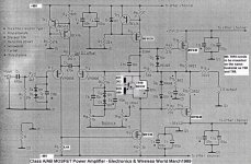
Is the one that appeared on Electronics Magazine on March, 1989, I think.
Is it this one?
The outputs are in the feedback loop, so even though they wouldn't be open (pure class B), you would still get decent sound. So when you say that you have "audible distortion", it must be the VAS not being open.
Please check that there is some current (22mA) flowing through TR7 - simply measure the voltage over R12. It should be something like 0.22V. If not, then increase R5 to 8,2K - 9.1k (or use a 22k trimmer to determin the value) .
When you get to the output transistors : The voltage over the trimmer R20 needs to be over 7V before the outputs open up, so while on the testboard -you could just increase the value of the trimmer.
HOWEVER....IRFs have thermal runaway (wich the K1058/j162 dont have) and therefore you need to replace the trimmer wth a proper bias circuit ( one extra resistor and one extra transistor)
An externally hosted image should be here but it was not working when we last tested it.
The outputs are in the feedback loop, so even though they wouldn't be open (pure class B), you would still get decent sound. So when you say that you have "audible distortion", it must be the VAS not being open.
Please check that there is some current (22mA) flowing through TR7 - simply measure the voltage over R12. It should be something like 0.22V. If not, then increase R5 to 8,2K - 9.1k (or use a 22k trimmer to determin the value) .
When you get to the output transistors : The voltage over the trimmer R20 needs to be over 7V before the outputs open up, so while on the testboard -you could just increase the value of the trimmer.
HOWEVER....IRFs have thermal runaway (wich the K1058/j162 dont have) and therefore you need to replace the trimmer wth a proper bias circuit ( one extra resistor and one extra transistor)
Last edited:

I'm trying to make it sound right, made my own PCB (checked, no mistakes), but I'm using dual 50V supply (actually, 53). The matter is I can't bias it, from both trimpots, still have distortion. I'm using IRF640-9640 as output (couldn't find K1058 or J162, yet), IRF530-9530 as drivers and BSS92 in differential stage, but I don't think this could be the problem.
Is the one that appeared on Electronics Magazine on March, 1989, I think.
The whole point of the amp is that it uses Lateral FET's
Try Nrik's bias generator (transistor should be on main heatsink to track outputs) if you must use HEXFET's.
The correct devices (later type numbers) should be readily available.
Magnatec. ALFET Lateral MOSFETs
Also 2sk1058 and 2sj162 are fine.
Interesting catalogue
Thanks, Mooly. Interesting catalogue here http://www.semelab.com/pdf/acc.pdf.
Max.
The correct devices (later type numbers) should be readily available.
Magnatec. ALFET Lateral MOSFETs
Thanks, Mooly. Interesting catalogue here http://www.semelab.com/pdf/acc.pdf.
Max.
Thanks a lot for all replies! I'll try all these mods! I know it was made for lateral mosfets, but I made some others and these vertical devices worked right! I know about thermal runaway, I'll use a proper heatsink and probably a cooler fan! Even with lateral ones.
Yup, that was the schematic!
Yup, that was the schematic!
Can you link to a copy of the schematics?
Notice that the IRFs need something like 3.2-3.8volt to open, where the K1058/J162 needs less than 1v, so maybe you just needs a higher voltage-drop in the bias circuit.
I have had problems getting the bias high enouh on amps with MOSFETs too.
The IRFP240 needs about 3.5 volts to turn on but the IRFP250 needs a bit more.
My first amp was a JLH amp and was 50 watts, brings back some happy memories of my first years in electronics.
It worked well for many years.
I used vertical mosfets in my guitar amp, using Flavio Dellepiane's 60W Mosfet Power Amp, and it hasn't a voltage multiplier, I even set up quiescent current so high that after 2 hours of playing (and pushed it really hard!) anybody can't almost touch the heatsink! IRF640-9640 work really well in that circuit.
Is it this one?
The outputs are in the feedback loop, so even though they wouldn't be open (pure class B), you would still get decent sound. So when you say that you have "audible distortion", it must be the VAS not being open.
Please check that there is some current (22mA) flowing through TR7 - simply measure the voltage over R12. It should be something like 0.22V. If not, then increase R5 to 8,2K - 9.1k (or use a 22k trimmer to determin the value) .
When you get to the output transistors : The voltage over the trimmer R20 needs to be over 7V before the outputs open up, so while on the testboard -you could just increase the value of the trimmer.
I forgot to try the 7V method, but tried a pot instead of 6.8k resistor, and still have distortion.
Turning the 200 ohm trimpot doesn't do anything, just the 2k2 trimpot makes sound less distorted when turned at max in one direction (didn't check if it was CW or CCW). Measured voltage across R5 (10 ohms) about 240 mV, so I think it was ok.
But if there is only 240mV over R5, then TR7 is not open. It needs at least 3.28volts to open up.
As I said: Increase R5 to 8,2- 9.1kohm, or try with a trimmer here ( 10k -22k)
Adjust until voltage over R12 is 240mV.
....waaaait a minute - 10 ohms? Is that really R5 and not R12 that you are measuring?
As I said: Increase R5 to 8,2- 9.1kohm, or try with a trimmer here ( 10k -22k)
Adjust until voltage over R12 is 240mV.
....waaaait a minute - 10 ohms? Is that really R5 and not R12 that you are measuring?
But if there is only 240mV over R5, then TR7 is not open. It needs at least 3.28volts to open up.
As I said: Increase R5 to 8,2- 9.1kohm, or try with a trimmer here ( 10k -22k)
Adjust until voltage over R12 is 240mV.
....waaaait a minute - 10 ohms? Is that really R5 and not R12 that you are measuring?
Sorry, it was R12, 10 ohms, about 240mV, so that's about 24mA. Adjusted bias por until I got about 8V across it, but the situation is the same. Also, replaced R5 with a 25kA pot, going from 7k to 25k and still the same...
I'm going to spend a bit more time with this circuit... I think drivers should be the same type as the schematic says... I don't remember if they were lateral mosfets.
Oh oh! I've just realised something: TR6 also needs about 3 volts, so, I should use a pot instead of that 22k resistor... or just change the 10V zener... what do you think?
Oh oh! I've just realised something: TR6 also needs about 3 volts, so, I should use a pot instead of that 22k resistor... or just change the 10V zener... what do you think?
No no - If you have current through TR7 then you are good.
TR6, R8, TR5 and R7 makes a constant current source ( CCS).
You will probably be able to measure 0.65V over R8, meaning that this part of the circuit is working correctly.
...and this is the strange thing, because when TR7 and TR6 is working, you should have a pretty much un-distorted sound.
Do you have an scope or only voltmeter. Because a scope measurement at R5 R9 and R14 would be nice.
What are your supply voltages (measured) for the input circuit and the output transistors?
Only have a multimeter!
 I'll measure input and output voltages... I turned the DC output trimpot just at 1 or 2 mV, but that made a lot of distortion, like unbiased sound! I think we'll get the problem point going this way...
Can I use a BD139 instead of a BC546 in the voltage multiplier part?
Yes you can.Can I use a BD139 instead of a BC546 in the voltage multiplier part?
Yes you can.
Thanks!
Some voltage readings:
Tr6: Vds = -50.6 V
Vgs = -3.73 V
Tr7: Vds = 44.6 V
Vgs = 3.71 V
Tr3: Vds = -49.1V Ids = 0.395 mA
Vgs = -1.4V
Tr4: Vds = -52.4V Ids = 0.405 mA
Vgs = -1.48V
VR8 = 0.665 V
V at Tr3 g = near 0V
Vgs at P Channel output mosfets = - 5.4 V
Vgs at N Channel outpur mosfets = 30mV
So this means only P-Channel are working, and that's why when I turned the DC offset trimpot fully at Tr3 I got some distorted sound... I'm not sure, but maybe Tr6 could be damaged, but I don't think so, it seems it's open!
Vgs at P Channel output mosfets = - 5.4 V
Vgs at N Channel outpur mosfets = 30mV
So this means only P-Channel are working, !
...At -5.4V betweeen gate and source it is definitely open. But when the Vgs is in the range of 3.1-3.3volt it is difficult to tell if the MOSFET is open, and at the same time, we need to know how much current runs thorugh them.
Too soon to tell. Your previous measurement indicated that is was conducting some 24mA....and that's why when I turned the DC offset trimpot fully at Tr3 I got some distorted sound... I'm not sure, but maybe Tr6 could be damaged, but I don't think so, it seems it's open!
Can you plese measure voltage over these resistors:
R4, R5, R12, R14, R15 ?
(Hint: when you know the voltage over the resistor, you can calculate the current running throug it with ohms law U/R=I. And that will be the current running throug the corresponding transistor!)
And voltage:
from R16 to ground ( offset voltage) ?
...okay- then it is good practice
R4 should be around 0.65V ( the EB diode in TR1) which gives around 0.8mA
R5 (Input stage) should show something like 3,7V ~ 0.4mA.
R8 and R12 should give you something between 20 and 25mA, and the current needs to be equal to make the smallest amount of DC offset.
R14 and R15 should have 22mV at 100mA idle-current. Adjust R20 until this is true.
Make sure you have fuses or 100ohm/1W resistors in the supply lines in case of the output MOSFETs going shortcircuit. ( I guess you know this, or maybe you allready made other precautions since you allready came this far - but if not then do it, it will save you money and time.)
- Status
- This old topic is closed. If you want to reopen this topic, contact a moderator using the "Report Post" button.
- Home
- Amplifiers
- Solid State
- Linsley Hood's all-mosfet power amp