behringer does clone them also ... in a very reliable way also i could say for a chinese made amp
the original goal was a PA amlifier that will be impossible to blow ...or lets say idiot proof ...amazing amps for subs but other than that their sound is average .... very usefull and more effective than typical class AB amps but still the sound quality is kinda lower than others
the original goal was a PA amlifier that will be impossible to blow ...or lets say idiot proof ...amazing amps for subs but other than that their sound is average .... very usefull and more effective than typical class AB amps but still the sound quality is kinda lower than others
Dear,
The old Crown Macrotech's with grounded Bridge where so awesome on the bass. All schematics are available on the crown website. Very interesting topology.
A dutch audiophile company called "van Medevoort" Used the same principe in the 90's on his monobloc amplifiers, with again awesome tight bass. He just used one big capacitor for the floating supply.
With kind regards,
Bas
Last edited:
hello, from where comes the floating supply amplifier topology ? Why are there so few commercial designs based on floating supplies ? Of course we have QSC, but apart from them ? I've seen the ALTEC-LANSING 9446A, kind of QSC copycat, but that's all.
By 'floating supply amplifier topology' I think you are referring to the QSC's MX series and other models where the load was connected between the center tap of the mains transformer and to ,what would normally be looked at as, the output of the amplifier.
Lets take the MX1500 for example. This design topology is very efficient but is less stable than a generic amplifier approach. The topology has to be heavily compensated for stability resulting in a lower slew rate relative to the amount of power these amps output.
The MX1500 is capable of an output of 1500W in bridge mode and has a slew rate of 20v/us. This is not very fast for this level of power and I think this amp would run into problems in the upper mid to high frequencies at high power levels.
I have heard many complaints about the sound quality of these amps when they are used for mid and high frequency applications. My response to that, IMO, was why would you use an amp for full range when it was intended for low frequency application. I'm not sure QSC would agree with this.
David.
Yes indeed when you look to a QSC MX schematic, it is incredibly simple and you get the impression that there is some magic enabling you to use a NE5532 opamp powered by +15V and -15V as input stage and driver, just before the big power transistors. There is no VAS (voltage amplifier stage) is such arrangement. This is quite confusing. Where are the components defining the slew rate ? What's the magic, actually ? And I still don't understand the topology if used in bridged mode like Crown Marcro-Tech 600 does. Any help much appreciated.The MX1500 is capable of an output of 1500W in bridge mode and has a slew rate of 20v/us. This is not very fast for this level of power and I think this amp would run into problems in the upper mid to high frequencies at high power levels.
I don't think you can compare the QSC circuit with the Crown Macro-tech 600, they are completely different. The Crown has basically two amplifiers per channel. One is for the audio and the other controls what side (+ or -) of the power supply gets grounded. There is NO center tap on the power xfmr and only one filter capacitor per channel. The only reference to ground for the power supply is the above mentioned "slave" amplifier. For a positive going signal the negative side of the power supply goes towards ground and vice versa. You can go to the Crown site and download the schematic to see what I'm trying to explain. The right side of the power section (high side) is for the audio and the left side is the power supply (low side).
Craig
Craig
I don't think you can compare the QSC circuit with the Crown Macro-tech 600, they are completely different. The Crown has basically two amplifiers per channel. One is for the audio and the other controls what side (+ or -) of the power supply gets grounded. There is NO center tap on the power xfmr and only one filter capacitor per channel. The only reference to ground for the power supply is the above mentioned "slave" amplifier. For a positive going signal the negative side of the power supply goes towards ground and vice versa. You can go to the Crown site and download the schematic to see what I'm trying to explain. The right side of the power section (high side) is for the audio and the left side is the power supply (low side).
Craig
Criag you are quite right there is no comparison between the Macro-tech series and the MX series. The MX series are class G amps with the so called floating supply. The Crown Macro-techs were a single ended supply with a virtual ground or otherwise known as a artificial ground. The job of the second output (low side amp) is to hold the ground potential at 50% of the supply rails. We can say that the output of the low side amp is held at ground. This topology avoids the need for an output capacitor allowing direct coupling of the high side amp with the low side proving ground and connected to the chassis.
I've never looked deep enough into this design to see if Crown was driving the low side amp with an inverted signal. If this was the case then each channel would be operating in an independent bridge mode.
Bridging left and right channels was possible because each channel had it's own power supply. With one channel driven from an inverted signal the voltage across the load could be doubled.
It was a rather elegant design but still I had a lot of these on my bench for repair. Usually small fires would start up on the boards causing enough damage to the boards to justify replacing entire boards. Crown was good enough to sell assembled boards, less the output transistors, at a very low cost of $25 US and $75 US for the input board.
The Macro-tech series sounded better at mid and high frequencies than the QSC MX series. But we have to keep in mind that commercial amps are not designed with fidelity in mind. They are designed to take a lot of S and abuse and keep on going.
David.
Yes, the low side is driven with an inverted signal. The last Crown I worked on was the 5000, was a PITA due to mucho disassembly and reassembly, plus it weighed a ton. All for lousy 47pf SM capacitor which was shorted.
Craig
LOL. Yes I remember the 5000. Crown didn't put much thought into what it would take to service those things. I think PITA is putting mildly.
David.
Yes indeed when you look to a QSC MX schematic, it is incredibly simple and you get the impression that there is some magic enabling you to use a NE5532 opamp powered by +15V and -15V as input stage and driver, just before the big power transistors. There is no VAS (voltage amplifier stage) is such arrangement. This is quite confusing. Where are the components defining the slew rate ? What's the magic, actually ? And I still don't understand the topology if used in bridged mode like Crown Marcro-Tech 600 does. Any help much appreciated.
Steph,
I think the 'magic' is in the fact that the whole power supply moves up and down with the signal. The supply for the opamps gets kind of bootstrapped that way, so no need for a Vas as such.
jd
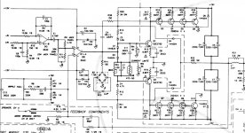
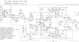
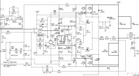
Yes, that's my understanding. When you look to the attached QSC 1400 or QSC MX700 schematic, how would you calculate the theoretical slew-rate ?I think the 'magic' is in the fact that the whole power supply moves up and down with the signal. The supply for the opamps gets kind of bootstrapped that way, so no need for a Vas as such.
Attachments
Last edited:
Yes, that's my understanding. When you look to the attached QSC 1400 or QSC MX700 schematic, how would you calculate the theoretical slew-rate ?
Hmmm, good question. In principle you would look for a node that has a capacitive load that is charged/discharged up to a high signal level with limited current, but to be honest I don't see that right away. I'll try to look at it some more later.
jd
On my side, I'll try simulating the QSC on LTspiceIV using a transistor-level TL071 model. We'll thus have access to the TL071 internal compensation capacitor so we'll be able to do some interesting variations on the theme. This may help.I'll try to look at it some more later.
Yes, that's my understanding. When you look to the attached QSC 1400 or QSC MX700 schematic, how would you calculate the theoretical slew-rate ?
The power supply needs to be shown with these amplifiers to gain an understanding of how they work. The ground potential is changing relative to the center tap of the transformer.
The load is connected between ground and the center tap.
In an earlier post I said the MX series were class G designs. I was referring to the second generation. MX1500A etc.
David.
Yes, that's my understanding. When you look to the attached QSC 1400 or QSC MX700 schematic, how would you calculate the theoretical slew-rate ?
The current limit of the opamp (about 40mA) together with the capacitor C4 (2.2nF) limits slew rate to about 20V/µs for large signals (it can go faster for small signals because of the series resistor), but other effects may limit it further. For one thing, current slew rate is limited by opamp output voltage slew rate together with output stage transconductance and this could become the limiting factor for heavy loads.
- Status
- This old topic is closed. If you want to reopen this topic, contact a moderator using the "Report Post" button.
- Home
- Amplifiers
- Solid State
- QSC audio - floating supply amplifiers