The current limit of the opamp (about 40mA) together with the capacitor C4 (2.2nF) limits slew rate to about 20V/µs for large signals (it can go faster for small signals because of the series resistor), but other effects may limit it further. For one thing, current slew rate is limited by opamp output voltage slew rate together with output stage transconductance and this could become the limiting factor for heavy loads.
But doesn't C4 also swing with the signal (both sides), except for the voltage actually across it? It must be the voltage across C4 that determines the charging requirements, no?
jd
or you could have said: the the time rate of change of the V difference across C4 determines the charging current
since one end swings with the output signal V you have to push "Miller multiplied" charge into C4 from the op amp output - or just do the calculation with the actual V difference rate of change by working backwards form Vsupply and sine wave max slope to get "power bandwidth" which is directly porportional to slew rate
the op amp output V however moves only a few V (if that) since it drives the grounded Q bases through a bias spreader with pretty low Z
Hi,
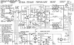
Short function description RMX1450, 2450: http://www.diyaudio.com/forums/atta...d1153853835-qsc-power-amp-qsc-rmx-details.pdf
According to above description the opamp output is 1V or less during normal operation. When the amp clips opamp output will rise considerably. Is C4 limiting slew (in a crude way) particulary during the latter condition?
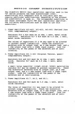
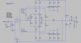
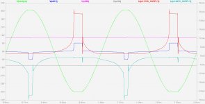
Just completed a LTspiceIV simulation workbench. Working nice, but I needed to idealize the power supply arrangement using two 51 Volt voltage sources in series with a centre tap. The "real" QSC has only one 102 Volt supply without centre tap. See attached files.
Attachments
or you could have said: the the time rate of change of the V difference across C4 determines the charging current
since one end swings with the output signal V you have to push "Miller multiplied" charge into C4 from the op amp output - or just do the calculation with the actual V difference rate of change by working backwards form Vsupply and sine wave max slope to get "power bandwidth" which is directly porportional to slew rate
the op amp output V however moves only a few V (if that) since it drives the grounded Q bases through a bias spreader with pretty low Z
If we are talking C6 in Steph's sim circuit above, the far side of C6 doesn't swing much, and neither does the opamp output. So despite it looks like the opamp is heavily cap loaded, it isn't that bad.
Too lazy to do the calcs...
jd
If we are talking C6 in Steph's sim circuit above, the far side of C6 doesn't swing much
It is connected to a node that is within a volt or so from the power supply which in turn follows the output signal. Remember, the power supply is floating!
The "far side" does have the full output signal swing. Some of the QSC circuits actually have it connected directly to the output node instead.
Last edited:
It is connected to a node that is within a volt or so from the power supply which in turn follows the output signal. Remember, the power supply is floating!
The "far side" does have the full output signal swing. Some of the QSC circuits actually have it connected directly to the output node instead.
Ahh yes! Thanks,
jd
Take a look at Jim Strickland's patented amplifier the TNT 200 marketed by Acoustat.
Quilter Sound has been around since 1968 and as far as I know, Pat Quilter was making grounded output amplifiers already in the mid / late 1970's. They aren't well known designs because back then Quilter Sound was making guitar amplifiers.
Versions of Pignose Crossmix 150R predate TNT-200 and the whole design is a descendant from an earlier Pignose 30/60 design, which was OEM product from Quilter Sound.
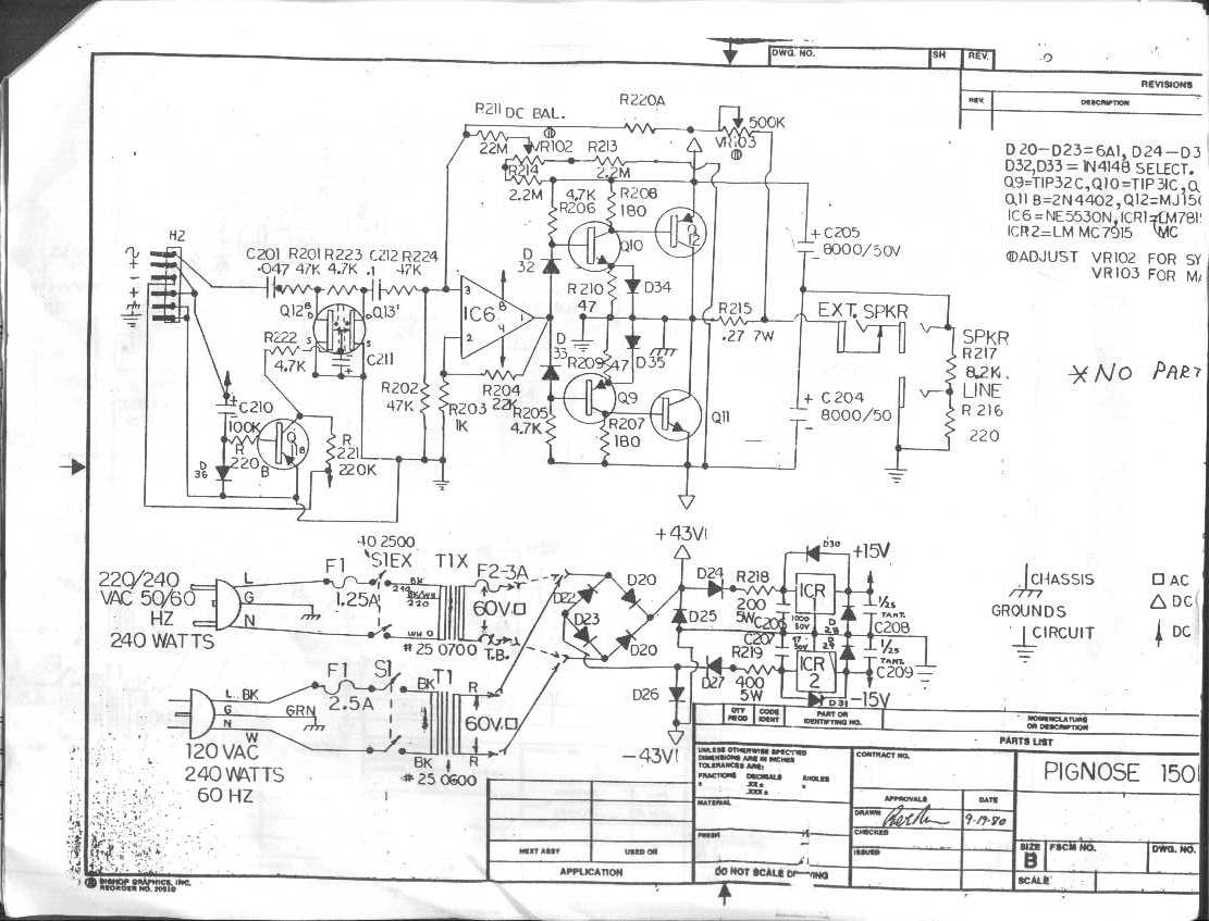
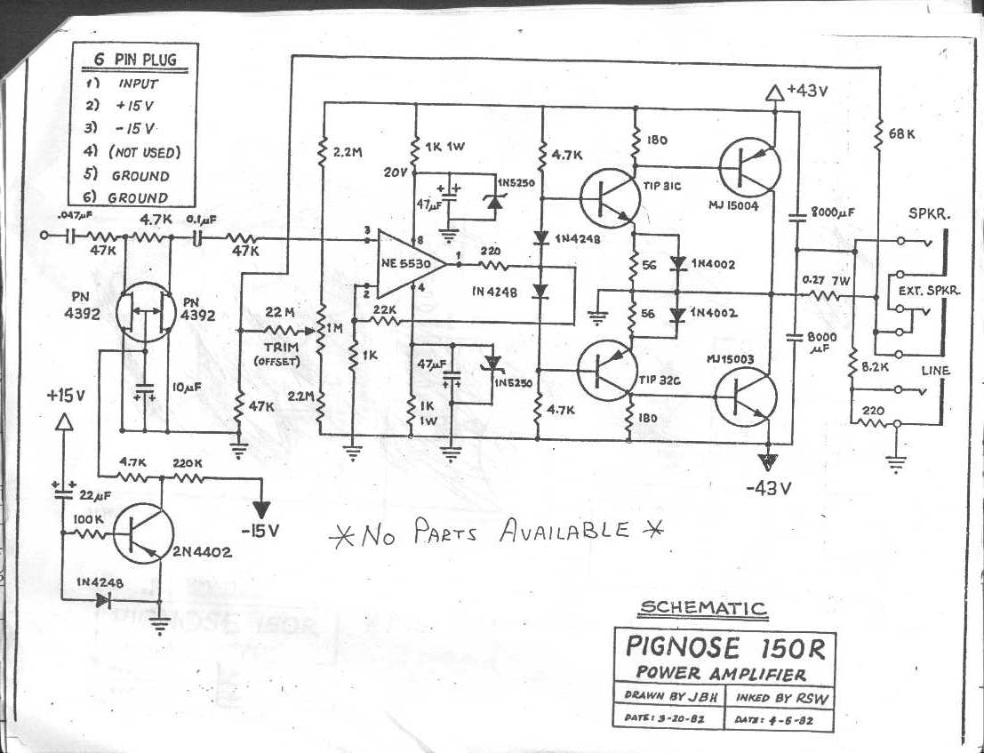
Has anyone here ever tried building one of these with an output *triple*? Or at least some other way of increasing output current capability? One of the biggest impediments to SQ in these old circuits is the highly load dependent output stage gm caused by beta droop. Moden driver/output devices have helped the situation, but there's only so much you can do with it. When the opamp runs out of gas at 40 ma, that's it - no more current for you. If you want an amp you can't destroy that's one way - but there are other methods that sound much better in practice.
I've has lots of trouble with sziklai triples in the past - and it would be needed if you wanted to keep the grounded collectors. I'm sure triple darlingtons would work - even in class H - but we're back to insulating the devices from the heatsinks. The other option would be a high current op amp - something that could deliver half an amp if you wanted it to - driving the normal QSC output stage. The opamps's supply wouldn't need to be derived from the floating supply - a separate +/-15 would do nicely. Anyone crazy enough to look into this yet? Of course, I'm thinking about applications larger than the RMX5050.....
I've has lots of trouble with sziklai triples in the past - and it would be needed if you wanted to keep the grounded collectors. I'm sure triple darlingtons would work - even in class H - but we're back to insulating the devices from the heatsinks. The other option would be a high current op amp - something that could deliver half an amp if you wanted it to - driving the normal QSC output stage. The opamps's supply wouldn't need to be derived from the floating supply - a separate +/-15 would do nicely. Anyone crazy enough to look into this yet? Of course, I'm thinking about applications larger than the RMX5050.....
Maybe you already know this, but some of the newer QSC circuits use triples:
http://www.qscaudio.com/support/library/schems/Current/PLX2 Series/PLX3602.pdf
http://www.qscaudio.com/support/library/schems/Current/CX Series/CX1202V.pdf
http://www.qscaudio.com/support/library/schems/Discontinued/PL2A Series/PL236A.pdf
These are not of the floating PSU kind, but the output stage configuration is still quite similar so they might be useful as inspiration.
The floating PSU kind can't be used on a switch mode supply - unless they want to build two of them ($$$$). I've always liked the sound of the PLXs because they get away from the inherent limitations of the classic circuit. I had hoped that they would do something like this with the 5050, but nooooo.
Sorry, it can be done, we have a SMPS with floating groundThe floating PSU kind can't be used on a switch mode supply - unless they want to build two of them ($$$$).
... This design topology is very efficient but is less stable than a generic amplifier approach. The topology has to be heavily compensated for stability resulting in a lower slew rate relative to the amount of power these amps output...
actually Dr Ed Cherry advocated for the use of grounded common emitter, floating supply outputs and claims in JAES articles that they they can have equivalent stability as an amp with the same devices in the more usual unity gain emiter follower output
this doesn't mean QSC amps are "properly" compensated or that using NE5534 gives enough speed or current drive
Last edited:
Sebastiaan;2216501 Interesting.[/QUOTE said:For sustained high outputs where the peak to average ratio is low (high level sine waves - like industrial control apps) the grounded bridge does have less stress on the output devices than any other linear topology. That is, if you can get the heat out. Efficiency can be no better than any other class B. Class H only really shines when you don't operate off the peaking supply on each and every cycle. Like audio. Peak stresses can be higher, but less heat.
The grounded bridge is actually a standard amp driving the high side of the speaker "married" to a QSC-style amp driving the ground. And the heat sinks are hot - it uses standard darlingtons on the low side insead of the grounded collector. In the end, it uses a heck of a lot of resources to accomplish the same end as a "Super-Leach" cascode, which also runs the transistors at lower VCE.
Like mentioned earlier, a Dutch high-end audio manufacture "van Medevoort" (Audioart producent van de van Medevoort geluids apparatuur) had a concept with a one capacitor floating power supply. However non of the sides of the bridged amplifier is grounded. They just had the whole circuit floating above ground and referred to the opposite phase. (the DC power supply rails and the audio lines). e.g. A compensation capacitor was connected between the + and - line input lines instead of signal and ground. I wonder why they choose this design approach. The benefit I can think of is no heavy pulses in the (now non excisting) ground line.
With kind regards,
Bas
With kind regards,
Bas
A compensation capacitor was connected between the + and - line input lines instead of signal and ground. I wonder why they choose this design approach. The benefit I can think of is no heavy pulses in the (now non excisting) ground line.
With kind regards,
Bas
It's probably cleaner that way from an audio perspective. BUT - the Crowns being commercial amps, one side of the speaker and one side of the input must be connected to earth ground.
It's probably cleaner that way from an audio perspective. BUT - the Crowns being commercial amps, one side of the speaker and one side of the input must be connected to earth ground.
But the whole power supply was also floating and no centre trap from the trafo. There was only one big philips cap between the + and - of the bridge. Even though different then the crown I wonder why they did that.
with kind regards.
Bas
- Status
- This old topic is closed. If you want to reopen this topic, contact a moderator using the "Report Post" button.
- Home
- Amplifiers
- Solid State
- QSC audio - floating supply amplifiers