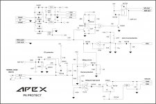
I don't know how to connect termal protection and where on pcb, haven't done it yet.
Usually I connect coolers(fans) direct to 12V power supply and they work full power all the time. Look at my DIY amplifier projects on this page:
http://www.diyaudio.com/forums/solid-state/168432-200w-pa-amplifier-2.html
Usually I connect coolers(fans) direct to 12V power supply and they work full power all the time. Look at my DIY amplifier projects on this page:
http://www.diyaudio.com/forums/solid-state/168432-200w-pa-amplifier-2.html
In that case fan make noise, and will be death for a few months, you can use circuit from my PA protect,I don't know how to connect termal protection and where on pcb, haven't done it yet.
Usually I connect coolers(fans) direct to 12V power supply and they work full power all the time. Look at my DIY amplifier projects on this page:
http://www.diyaudio.com/forums/solid-state/168432-200w-pa-amplifier-2.html
Regards
Attachments
check out this thread for more ideas:
http://www.diyaudio.com/forums/soli...-models-quasi-complementary-power-output.html
http://www.diyaudio.com/forums/soli...-models-quasi-complementary-power-output.html
Thank's 2N3055 is also legend as 2N3773,check out this thread for more ideas:
http://www.diyaudio.com/forums/soli...-models-quasi-complementary-power-output.html
Regards
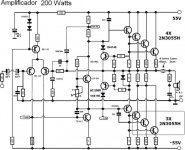
It is not much similar, to high rail voltage even for 2N3055H, and can't work in class B (to much crossover distorsion),Hi Apex
I found this circuit from the net. It seem similar of yours.
I have a question. Can it run in class B and how many output current biasing?
Sorry for my bad english. Thank you.
Regards
helpful informations about this topology you will find about follow URLs and attached PDF files:
http://www.passdiy.com/pdf/citation.pdf
http://www.diyaudio.com/forums/solid-state/165165-edwin-20-watt-elektor-1970-may-3.html
http://www.diyaudio.com/forums/solid-state/113943-quad-303-triple-cascade.html
Stabilized rail-to-rail speaker driver circuit
http://www.bgaudioclub.org/uploads/docs/High_Performance_Audio_Power_Amplifiers,_B.Duncan.pdf
Attachments
-
QuadTriple.PDF9.5 KB · Views: 728
-
QuadTripleFigs.pdf24.7 KB · Views: 500
-
Symmetry in class b Bax.pdf164.7 KB · Views: 647
-
Quasi-compl. Mod.Shaw Figs.pdf58.2 KB · Views: 482
-
Quasi-Compl. Amp H.C.Lin.PDF18.5 KB · Views: 557
-
Quasi-Compl. Amp H.C.Lin Figs.pdf29.7 KB · Views: 595
-
Quasi-compl. Mod.Shaw.PDF10 KB · Views: 485
-
Sziklai www.ibiblio.org bjtamp_b.pdf104.6 KB · Views: 575
Last edited:
")
about follow website you will find more interesting approaches:
Audio Amplifier Design
Audio Amplifier Design
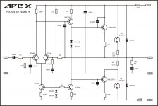
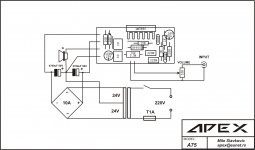
At my view beginners should not start with an high power audio amp circuit appropriate for supply voltages between 80V until 160V !!!There always be begginers, and some people with expirience go back to this simple design 20 years after they build first one. This is clasic circuit as bridge rectifier, and always will be usefull,
Regards
20-40 volts (+/-10 - +/-20 volts) are enough for starters and first projects. Because this means much lower output power, more amp devices and multi-amping modes resp. active crossover solutions are necessary.
The great advantage by carried out this solution is the possibility to go on in steps (at first small amp, after checking the reliability the clone of more such devices and as last step an active crossover network).
BTW - in the schematic from previous post I would introduce additional resistors in the collector lines of the BC546, so that the voltage from C to E arround 20-25 volts
Last edited:
For absolute begginers,
http://www.diyaudio.com/forums/chip-amps/162099-lm3886-schematics-pcb.html
Regards
http://www.diyaudio.com/forums/chip-amps/162099-lm3886-schematics-pcb.html
Regards
Attachments
Stereo with PSU
http://www.diyaudio.com/forums/chip-amps/162179-tda7294-stereo-bridge-psu.html
Regards
http://www.diyaudio.com/forums/chip-amps/162179-tda7294-stereo-bridge-psu.html
Regards
Attachments
Power is not that important, this is simple schematic with no adjust. Begginers may have problem with any amp no metter what power it is.At my view beginners should not start with an high power audio amp circuit appropriate for supply voltages between 80V until 160V !!!
20-40 volts (+/-10 - +/-20 volts) are enough for starters and first projects. Because this means much lower output power, more amp devices and multi-amping modes resp. active crossover solutions are necessary.
The great advantage by carried out this solution is the possibility to go on in steps (at first small amp, after checking the reliability the clone of more such devices and as last step an active crossover network).
BTW - in the schematic from previous post I would introduce additional resistors in the collector lines of the BC546, so that the voltage from C to E arround 20-25 volts
About resistors in the collector... This is oldest schematic version, I add cascode, current miror, VI limiter, bias adjust... but that is new amplifier,
Regards
Hi guys i am willing to trade a one dhr turbo board industry standard for the two quasi board of any quality as long as it does the job.
or dx blam es boards two of them for two of quasi board. the dx blame es - one of the board is complete with parts and transis. i would like one of the quasi boards to atleast come with some parts resistors and caps not big issue but would like to have the little transistors the 2n773 dnt matter but welcome it if offered.,
or dx blam es boards two of them for two of quasi board. the dx blame es - one of the board is complete with parts and transis. i would like one of the quasi boards to atleast come with some parts resistors and caps not big issue but would like to have the little transistors the 2n773 dnt matter but welcome it if offered.,
- Home
- Amplifiers
- Solid State
- QUASI Amplifier for Beginners