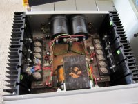
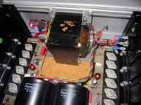
Hello! I just bought a "not working" Perraux 2150B for $200. It's a monster, huge caps, nice chassis, plenty of room.
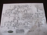
Schematic and pix attached, will e-mail you the .pdf schematic upon request.
I figured that if the mosfets were toast I could build my own boards and have a nice amp.
I just cracked it open, before plugging it in I took the positive wire off of the rectifier, the one that runs to the big caps. So I could start out by testing the transformer and the rectifier.
To my suprise It's 150VDC out of the rect. and 133VAC out of the trans. The specs call for 82VDC rail and 62.4VAC.
So my transformer must be toast right? As must be the mosfets because they were fed a diet of 150VDC instead of 82? Could it be a bungled 220V conversion, any ideas??
Can one get a transformer fixed or replaced? Any help would be greatly appreciated.
Thanks,
John from Minnesota!
Attachments
Nice, I had a 1050B and turned it into a F5. the F5 is far more detailed through bass mid and highs, however your 2150 plenty of volume. you may find your rectifier and caps need replacing, and possibly a transistor or 2.
But id be using the case and heat sinks, and dropping a new module in it, plenty available.
Where you live ?
But id be using the case and heat sinks, and dropping a new module in it, plenty available.
Where you live ?
I'm sorta new to electronics repair. I thought the the red wire was "hot" and the black one would be neutral... Duh! it's DC!
How does one determine if the rect needs replacement? I'd have to replace that even if I used modules. I assume you are referring to the small cap's? How do I test the transistors, it does seem to sound fine?
NEXT...
I am not fimilar w/ the F5, got a link?. Who has the best mosfet design (module) that doesn't get too hot? Classe, McIntosh, Pass, Levenson???
I'm in Minnesota USA.
These amps are made in N.Z. so they are a bit of a legend over here and its been interesting watching there success and growth. High End Audio Amplifiers for Audiophiles : Home - Perreaux (International)
Keep in mind the old saying "If it arnt broke dont fix it"
F5 is here http://www.diyaudio.com/forums/pass-labs/121228-f5-power-amplifier.html
how evey its best sounding amp you may ever hear its only around 25 watts.
keeping in line with what you have try something like this amp module
8 PWR BJT AMPLIFIER BASED ON 2SC5200 2SA1943 200W+200W - eBay (item 190398436625 end time May-24-10 20:11:55 PDT)
But if your not game to fiddle then these guys who will give you support.
Holton Precision Audio Online Store - Audio Electronics -
also this is more important to do first as there is no speaker protection on your amp and it will do someday what mine did and short out and send DC straight to speakers and burn them out before your had time to turn amp off. so install this:
40A Turn-on Delay, Loudspeaker Protection Module DIY - eBay (item 160399970759 end time May-30-10 21:17:16 PDT)
What component failed that made you amp blow the speakers?MOSFET tran- when things go wrong somewhere in the circuit they can send high currant DC straight to speaker like a heavy base sound but not fluctuating as a base sound normally goes boom boom a dc short will be one long booooooom which cause wire on speaker coil to overheat and burn out to the extent you can see smoke coming out of the speaker port.
An externally hosted image should be here but it was not working when we last tested it.
Last edited:
That's a good amplifier.
Just replace all the small electrolytics, don't mess with the transistors.
If you want a bit more high frequency detail, bypass the input coupling cap, and the one in the feedback loop with some small film types (0.01µF~0.1µF).
yep, listen to this man
")
- Status
- This old topic is closed. If you want to reopen this topic, contact a moderator using the "Report Post" button.
- Home
- Amplifiers
- Solid State
- Transformer issues? Perreaux 2150B Pix, Schematic...