Member
Joined 2009
Paid Member
Following on from the last design [http://www.diyaudio.com/forums/solid-state/145652-tgm2-amplifier-12.html] I want to see if the design can evolve to achieve better sound. I have some single rail transformers, so this will be a Single Rail design with an output capacitor(s).
For inspiration I have started by looking at the Quad 303. It's an amplifier which came before the famous current dumping designs but people who have listened to both say they prefer the 303 (partly because the 405 was so poorly implemented).
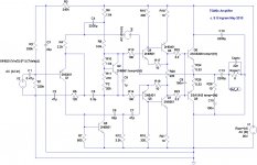
The Quad 303 uses the same bootstrap VAS as my prior designs. With a Single Rail supply it uses a single input device instead of an LTP. It also uses output triples with quasi-complimentary power devices. For TGM3 I'm going to adopt the triples but use a complimentary output. No doubt my version will sound completely different - so be it, I'm not trying to clone the Quad.
Attached is my current approach.
Note that I'm not looking for gobs of power considering that I've only got 36V to play with. So I've used small signal devices everywhere. Simulations say they won't catch fire
Whadya think ??
For inspiration I have started by looking at the Quad 303. It's an amplifier which came before the famous current dumping designs but people who have listened to both say they prefer the 303 (partly because the 405 was so poorly implemented).
The Quad 303 uses the same bootstrap VAS as my prior designs. With a Single Rail supply it uses a single input device instead of an LTP. It also uses output triples with quasi-complimentary power devices. For TGM3 I'm going to adopt the triples but use a complimentary output. No doubt my version will sound completely different - so be it, I'm not trying to clone the Quad.
Attached is my current approach.
Note that I'm not looking for gobs of power considering that I've only got 36V to play with. So I've used small signal devices everywhere. Simulations say they won't catch fire
Whadya think ??
Attachments
Last edited:
See where your OLG meter source is? It looks to me like the bootstrap cap is drawing current through it, which contaminates any feedback measurement. You should probably move the bootstrap to the right of the source.
If you plan on running this without a center-tapped trafo, I'm interested in what you think of the minimalist virtual ground I posted about in the TMG2 thread shortly ago.
- keantoken
If you plan on running this without a center-tapped trafo, I'm interested in what you think of the minimalist virtual ground I posted about in the TMG2 thread shortly ago.
- keantoken
Last edited:
Member
Joined 2009
Paid Member
I may toy with the virtual earth, but it seems like it just moves the output cap from one side of the speaker to the other side - and requires more caps in total. I've built one on a small piece of perf board. I also tried it with active devices to hold the centre voltage more firmly than the resistors alone but I haven't done listening tests with it.
Thanks for the tip on the OLG meter, I'll try moving it and see what changes. With the OLG meter I'm really looking at voltages, the meter has perfect zero resistance - so perhaps current flow into the bootstrap cap won't matter ?
Thanks for the tip on the OLG meter, I'll try moving it and see what changes. With the OLG meter I'm really looking at voltages, the meter has perfect zero resistance - so perhaps current flow into the bootstrap cap won't matter ?
I am going to move my discussion to this thread now...
Basically what I'm saying is that the cap is no longer directly in series with the speaker - after this now the amplifier has a chance to correct for any distortions caused by it (them). The amp does not care where, with respect to rails, ground is. The amp simply uses ground as a reference; it makes a voltage difference between ground and speaker input. Any distortion caused by the caps only moves the ground reference up or down with respect to rails, and the amp is designed to ignore this as long as power ground and input ground remain the same. When you disconnect input and power ground, the caps essentially become in series with the speaker again.
I realized my explanation in the other thread was lacking... I hope this makes more sense.
While at higher frequencies the cap distortions may slip past the feedback of the amp, this goes for all ambient distortions (I call them ambient because they are induced by rail modulation and peripheral things that the amp is intended to be able to filter out).
If you're not measuring current through the meter, it should be fine. Again, maybe neural pruning...
- keantoken
Last edited:
Member
Joined 2009
Paid Member
Do you mean that the power rails are supposed to float wrt virtual ground? You'll want to remove those resistors from the virtual earth or ensure they are of high resistance so that they can float.
This capacitor only virtual earth scenario was recommended by Jean Hirage in his Le Monstre as an option. However, I am concerned that without separate transformer windings for L and R channels there could be a fair bit of cross talk because the two channels will 'talk' via the power rails.
My transformer has only one secondary and needs to feed both L and R channels (in the current set up I can't fit two transformers into the Chasis - I have 4 transformers available and I suppose I could use a large chasis if I had to)
Last edited:
Why remove the resistors? This would cause total DC blocking, which would disable the amp. It needs an external bias to keep it near the middle (by relieving rogue DC necessary for input bias current, etc.), and the resistors are for this purpose. Also consider output offset; if the offset is not adjusted and the resistors are too high, the ground will bump up against the rails and may be too sensitive to DC offset to get ground in the right place. I would make the quiescent current of the resistors at least 10 times the total DC current that runs from the rails into ground, hopefully more. For this amp, the only DC running through ground will be Q1's Ib, so you could easily get away with higher value resistors, though I would have at least several mA quiescent current so there are no complications for offset adjustment (when offset is adjusted to zero, ground will also be in the middle of the rails since there is minimal DC to disrupt the balance between resistors).
You could use a different virtual ground for each amp and that would pretty well separate the paths, save for rail modulation which will happen regardless of grounding scheme.
- keantoken
You could use a different virtual ground for each amp and that would pretty well separate the paths, save for rail modulation which will happen regardless of grounding scheme.
- keantoken
Last edited:
Member
Joined 2009
Paid Member
Whilst I think about output capacitors perhaps I should simply use the TGM chasis I already have. Now that I've given up on TGM1 I have additional space in the box because it's designed to allow up to 5 channels and so far only 2 are in use.
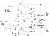
Now we can use dual rails and the output capacitor can be removed.
I may even be able to modify the existing TGM pcb layout without having to start over
Now we can use dual rails and the output capacitor can be removed.
I may even be able to modify the existing TGM pcb layout without having to start over
Attachments
Member
Joined 2009
Paid Member
I haven't experimented with C2. It's main function is for charge suck-out and I remember settling on 100nF as a value that has been popular. If I remember correctly I used 150nF because the larger cap made pcb layout easier
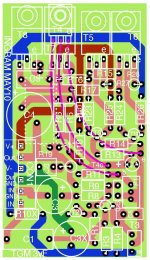
Looking at the home made pcb from TGM2 it doesn't look too hard to shuffle things around to make up something for TGM3. Heres' the first attempt...based on single pole compensation.
Looking at the home made pcb from TGM2 it doesn't look too hard to shuffle things around to make up something for TGM3. Heres' the first attempt...based on single pole compensation.
Attachments
Member
Joined 2009
Paid Member
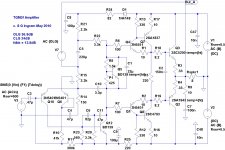
Shouldn't there be a filter cap between R10 and R5? I thought that was the original idea.
Also, you use the output as the VAS bootstrap reference, but the voltage difference between the input and output of the output stage is not linear, which will inject distortion into the VAS (primarily odd order). The idea is to have equal AC on each side of R6 so it effectively works as a CCS. I suggest to move the bootstrap reference to the collector of T5. The voltage here is much closer to the VAS voltage, and with the outputs out of the way, much of the odd harmonics are gone. Also, I found putting the reference on the other side of R15 will give a different harmonic signature; you may want to experiment, I haven't been able to.
- keantoken
the bootstrap C4 would have to charge the filter cap. That would be extra load for the bootstrap.Shouldn't there be a filter cap between R10 and R5?
R25 passes ~1.8mA bias and R15 passes ~5mA bias.
These values result in T5 passing only 3.2mA bias. This seems very low.
The output base stoppers (8r2) seem to be very high in value. I'm guessing that stopper Vdrop~20mV
Would adding base stoppers (10r?) to the drivers, T5 & T6, have any advantage in stabilising the the CFP?
C3 seems very low in value. Does this amp get used for bass or wideband duty?
Last edited:
Bigun, often I find myself doing this:
1: probe both Ic(T3) and I(R6) to see just how much VAS power is being eaten by R6. The voltage between input and output of the output stage swings as much as 3V, and this is imposed across R6.
2: To see the nature of the distortion injected into the VAS by the bootstrap reference, plot the trace d(I(R6)). d(x) plots the time derivative if the signal and this will emphasize crossover errors.
Usually I find a different bootstrap point, and repeat. I've just been playing in the simulator and rediscovered the details of this bootstrap stuff. If you take reference from either side of R15, you'll get a rectified wave. Less load for T3, but now we're injecting a rectified waveform into the VAS. I found the optimal solution was to split R15 in half and take the bootstrap reference from that point. Better yet, use two bootstrap caps, one taken from each side of R15. This way gives the most benefit since R15's voltage drop does not interfere. (EDIT: In my simulations, this last solution drastically decreases the VAS load. Now the bootstrap eats only 1/3 of T3's current, whereas before it ate the vast majority of it. Since the output devices are no longer in the bootstrap loop, most of the higher harmonics have been eliminated as d(x) will reveal)
BTW, you can also tune the output stage bias using the d(x) function. Plot the voltage difference between the input and output of the output stage (using the d(x) function) and then adjust bias for the smoothest sine.
- keantoken
Last edited:
Member
Joined 2009
Paid Member
Thanks everyone for some helpful questions !
First off, I am trying to get to a working experiment as soon as possible. This means re-using the pcb design from TGM2 since it will then 'drop in' to the existing chasis which means just plugging in the single multi-way connector carrying all the power and signals. That board already has 3 large caps on it, C4 and C3 and C3X, being the bootstrap cap and the two power rail caps respectively. The original design used a small 22uF bipolar feedback shut cap. For TGM3 it needed a larger cap. In TGM2 the + rail PSRR relies on the rail capacitor to keep noise out of the LTP. With TGM3 we have a Singleton that is not biassed using the + rail and the VAS supply is kept clean by the bootstrap cap. As Andrey points out, the rail cap is redundant and only adds to the bootstrap load so I repurposed this capacitor and used it for the feedback shunt capacitor and so C3 is now 100uF. I could use a larger cap so long as it has the same footprint, but my junk box has a few Nichicon MUSE 100uF caps waiting... the amp is mostly a project to build and listen, starting life as a stereo it's eventual home will be for a satellite channel for my HT system so it won't see much bass.
I haven't looked at the impact of moving the Boostrap cap take off point. Simulations (aren't they nice !) show that odd harmonics are already very low and pretty much inaudible but it sounds like a fun experiment I can try out.
Is the output a Triple ? - well perhaps not in the strict sense that the Quad 303 was a triple but I wanted to incorporate the benefits of what Self calls a Type II EF output in which the topology (including C9) helps with output device turn off by pulling out minority charge from the bases of the devices turning off.
I originally started with small signal devices so I didn't want too much current through the drivers but by reusing the TGM2 design I'll have a nice pair of good drivers bolted to the main heatsink. I could certainly increase the current by dropping R15. This pushes up power dissipation - I'm not sure how much, if any, sonic benefit ?
The pre-drivers are kept at a low biass to reduce loading on the VAS. In fact I think of the pre-drivers as a VAS buffer and I have considered running Cdom from the emitter of the first pre-driver instead of from the VAS collector. Simulations didn't show any benefit from this however ??
Output base stoppers, yes, should be reduced to something closer to 3R3. I didn't use stoppers on the drivers because neither did Quad. I've read that these triples are hard to stabilise and I assume that Quad did a fair bit of work to get it right so I"ve sprinkled resistors where they did ?
edit: Kean - some great ideas re: bootstrap. I don't know if I can accommodate them on my pcb but I sure can try them with a fly-wire mod.
I'm OK with the pre-driver bias current. This is set by the 330r.
It's the driver bias that is going off the low end of the datasheet. My datasheet only goes down to 5mA and it looks like fT <20MHz @ Ic<4mA
I would guess that 30 to 40mA of bias would bring about a much more stable fT as output current changes. There are massive swings in driver current as output current varies.
If the amp will not get used for bass signals then change the input high pass filter. There is no advantage to increasing the AC signal across the feedback DC blocking capacitor.
Last edited:
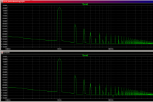
Okay, I've just looked at the FFT's for the bootstrap option specifically. What I find interesting is that the ONLY change is in the 5th harmonics (by 11db)! Strange, but if it's audible, it might be revealing.
Net THD is only slightly lower.
- keantoken
Net THD is only slightly lower.
- keantoken
Attachments
- Status
- This old topic is closed. If you want to reopen this topic, contact a moderator using the "Report Post" button.
- Home
- Amplifiers
- Solid State
- designing TGM3 - output Triples