Hey guys!
I'm trying on building some nice simple ultra low noise amp with noise values below the 1 nV/rtHz level. Read many papers and threads about that topic and built up several little amps with low noise JFET's like 2SK170, 2SK369 and IF3601. I use them in source mode going into a non-inverting Opamp LT1028 as second stage. My noise values and bandwith are good.. reached like 0,3 nV/rtHz and bandwith up to 1 MHz. So that's good, but what's not so good is the THD ! Often I got like 3-6 harmonics resulting in THD's of 0,5 to 3% so that's way too high for my application. I need some value below 0,1%.
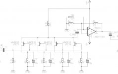
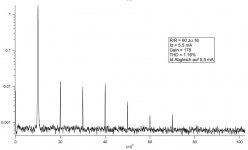
Biassettings of the 2SK170 for example are like Uds = 8V , Ugs = -0,12V and Id = 6 mA. So those values should work out for good linearity in the input and output curves. But they don't :-( Mostly I get strong second harmonic.
I put up my basic schematic and a picture of those bad harmonics I get, hoping that anyone knows how to effectively reduce that THD!! Or is it not possible in a source-circuit to drop the THD below 0,1% ? Do I need some complementary stage or feedback to get better?
Supply voltage is +-12V not 5V and signalsource is like 10kHz with 10mVpeak.
Thanks for your answers,
Greetings
Tobi
I'm trying on building some nice simple ultra low noise amp with noise values below the 1 nV/rtHz level. Read many papers and threads about that topic and built up several little amps with low noise JFET's like 2SK170, 2SK369 and IF3601. I use them in source mode going into a non-inverting Opamp LT1028 as second stage. My noise values and bandwith are good.. reached like 0,3 nV/rtHz and bandwith up to 1 MHz. So that's good, but what's not so good is the THD ! Often I got like 3-6 harmonics resulting in THD's of 0,5 to 3% so that's way too high for my application. I need some value below 0,1%.
Biassettings of the 2SK170 for example are like Uds = 8V , Ugs = -0,12V and Id = 6 mA. So those values should work out for good linearity in the input and output curves. But they don't :-( Mostly I get strong second harmonic.
I put up my basic schematic and a picture of those bad harmonics I get, hoping that anyone knows how to effectively reduce that THD!! Or is it not possible in a source-circuit to drop the THD below 0,1% ? Do I need some complementary stage or feedback to get better?
Supply voltage is +-12V not 5V and signalsource is like 10kHz with 10mVpeak.
Thanks for your answers,
Greetings
Tobi
Attachments
Hi, with small input the 2SK170 can do 0.003 - 0.005%.
See Table 2 and 3 here: Audial DIY :: Module LAB :: Preamp
Also see interesting discussion here: http://www.diyaudio.com/forums/solid-state/165961-simple-60db-discrete-low-noise-amplifier-lna.html
See Table 2 and 3 here: Audial DIY :: Module LAB :: Preamp
Also see interesting discussion here: http://www.diyaudio.com/forums/solid-state/165961-simple-60db-discrete-low-noise-amplifier-lna.html
Last edited:
The VGS matters
You must remember that the input level must be low, much lower than 0.12 V, to get some descent THD figures. Otherwise you will have to increase the source resistor (increasing the noise) to increase VGS and lower the drain current. I think the simplest solution would be to include the FETs in the OPAs feedback loop.
You must remember that the input level must be low, much lower than 0.12 V, to get some descent THD figures. Otherwise you will have to increase the source resistor (increasing the noise) to increase VGS and lower the drain current. I think the simplest solution would be to include the FETs in the OPAs feedback loop.
Hey guys, thanks for your answers!!
source impedance will be some coil for detection of magnetic field... somewhat with parameters like R = some Ohms (DC), L = some µH and selfwound. perhaps some coupling transformer will be added to that in the input stage. so thats why I chose JFET's with high input impedance.
but at this time I don't really know what signallevel will come to amplify. I think some mV. So let's assume 10 mVpeak. That should be small enough for Ugs = 0,12 V ?!
Would be still in the linear part of the transfer curves of 2SK170 with Idss like 10 mA (BL). I matched 4x 2SK170 with Idss = 10 mA.
The ULNA is not for audio (should I say that on this forum?!) but it's quite the same because my bandwidth starts at 1 kHz up to max. 1 MHz. (ok thats not so audio-like but it's very similar to those phono amp designs..) and it should be usable for audio, too. so that's why corner = 90 Hz... doesn't really matter - main signal frequency starts at some 10 kHz or so...
You got some example how to include the JFET's into the feedback loop of the opamp? I just found some quite complicated ones.. so the main thing is changing the opamp into inverting-type and give back the output over some coupling R or C to the Source of the JFET's?? How does that effect the bandwidth of the amp? Often there are additional Transistors set to Source and Drain contact of the Main JFET in order to control or balance the Drain-current?! Do those Transistors help with the THD? or what is the need for those?
I add some example schematic of those complicated feedback loop amps, but it's with discrete second stage, too.
So I'll try out some Amp with feedback, I'll simulate it first in Spice and see what I get there") But more informations and comments are welcome !!
But more informations and comments are welcome !!
source impedance will be some coil for detection of magnetic field... somewhat with parameters like R = some Ohms (DC), L = some µH and selfwound. perhaps some coupling transformer will be added to that in the input stage. so thats why I chose JFET's with high input impedance.
but at this time I don't really know what signallevel will come to amplify. I think some mV. So let's assume 10 mVpeak. That should be small enough for Ugs = 0,12 V ?!
Would be still in the linear part of the transfer curves of 2SK170 with Idss like 10 mA (BL). I matched 4x 2SK170 with Idss = 10 mA.
The ULNA is not for audio (should I say that on this forum?!) but it's quite the same because my bandwidth starts at 1 kHz up to max. 1 MHz. (ok thats not so audio-like but it's very similar to those phono amp designs..) and it should be usable for audio, too. so that's why corner = 90 Hz... doesn't really matter - main signal frequency starts at some 10 kHz or so...
You got some example how to include the JFET's into the feedback loop of the opamp? I just found some quite complicated ones.. so the main thing is changing the opamp into inverting-type and give back the output over some coupling R or C to the Source of the JFET's?? How does that effect the bandwidth of the amp? Often there are additional Transistors set to Source and Drain contact of the Main JFET in order to control or balance the Drain-current?! Do those Transistors help with the THD? or what is the need for those?
I add some example schematic of those complicated feedback loop amps, but it's with discrete second stage, too.
So I'll try out some Amp with feedback, I'll simulate it first in Spice and see what I get there
But more informations and comments are welcome !!Attachments
Perhaps you should have a look at this other thread, we've been talking about something similar. Starting with post #126
http://www.diyaudio.com/forums/soli...e-low-noise-amplifier-lna-13.html#post2192239
we were discussing a transformer input amp that capable of very low noise.
http://www.diyaudio.com/forums/soli...e-low-noise-amplifier-lna-13.html#post2192239
we were discussing a transformer input amp that capable of very low noise.
Reducing Distortion with JFET Front End
Another effective approach is to utilize a symmetric front end with both N and P channel devices. You will want to match at least Idss for devices of a given polarity. The distortion caused by differences between the N and P devices can be reduced by connecting the N and P devices' outputs together with a capacitor that yields an RC frequency in the 1-10 Hz range. This allows the amp to maintain the proper DC operating points but effectively parallels the upper and lower halves of the diffamp at AC frequencies. I have simulated such a design with up to 10 mVPP, and have consistently obtained distortion levels well below the noise floor of approx 0.3 nV/sqrt(Hz). Using 74/170 FETs gives an AC gain of approx 22 dB for the JFET front end.
Another effective approach is to utilize a symmetric front end with both N and P channel devices. You will want to match at least Idss for devices of a given polarity. The distortion caused by differences between the N and P devices can be reduced by connecting the N and P devices' outputs together with a capacitor that yields an RC frequency in the 1-10 Hz range. This allows the amp to maintain the proper DC operating points but effectively parallels the upper and lower halves of the diffamp at AC frequencies. I have simulated such a design with up to 10 mVPP, and have consistently obtained distortion levels well below the noise floor of approx 0.3 nV/sqrt(Hz). Using 74/170 FETs gives an AC gain of approx 22 dB for the JFET front end.
If you are feeding this amplifer with a source of a few uH and a few ohms, try a bipolar front end. Its quite easy (in simulation anyway) to get distortion figures with low level inputs (say up to 10 or 20mV) of under 1ppm. For some ideas, look up Syn08 on the forum. He did an ultra low noise, low THD front end amp for an RIAA amplifer. The front end amp has a flat response, so this would suit your requirements.
for this reason I don't like jFETs like 2SK147, 2SK170, 2SK389. I want to use such jFET's in general by versions with low Cin. unfortunately such versions from process 50 have low values for Gm. Therefore, suitable additional steps to increase Gm are also necessary.what are source impedance, signal level for the distortion # ? - nonlinear Cin is sometimes an important effect at higher Zin
check out post #54 under
What JFET should i choose for a preamp?
I think you mean a fully complementary differential amp resp. LTP (e. g. with 2SK389/2SJ109 - check out the datasheets for Cin of both).Another effective approach is to utilize a symmetric front end with both N and P channel devices. You will want to match at least Idss for devices of a given polarity. The distortion caused by differences between the N and P devices can be reduced by connecting the N and P devices' outputs together with a capacitor that yields an RC frequency in the 1-10 Hz range. This allows the amp to maintain the proper DC operating points but effectively parallels the upper and lower halves of the diffamp at AC frequencies. I have simulated such a design with up to 10 mVPP, and have consistently obtained distortion levels well below the noise floor of approx 0.3 nV/sqrt(Hz). Using 74/170 FETs gives an AC gain of approx 22 dB for the JFET front end.
I don't like this topology, because there are large differences between N- and P-CH jFET (I haven't heard until now an amplifier in this topology for front-end with really good sonic performance).
For this reason I start the last thread from above mentioned URL.
Last edited:
- Home
- Amplifiers
- Solid State
- Ultra low noise amp with JFET's - How to reduce the THD ??