Hi!
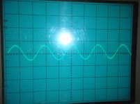
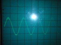
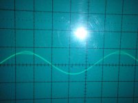
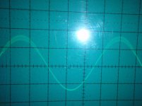
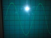
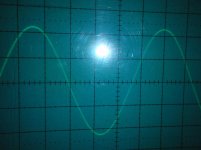
I have put together an amplifier based on a design by G. Randy Slone, with some modifications. The problem is I get some weird oscillations on the positive half period. They start at a peak value at about ~8 volts, and continue to about ~30 volts peak value (measuring on the output). After this the top of the curve is ok, but it is still oscillations below ~30 volts. Hard to explain put see the attached pics, they explain better than words.
Because of the NFB, this oscillation spreads in the entire amplifier so I cannot locate the source. Do anyone have any ideas.
Thanks
Attachments
I agree with Jaycee, change Q8, a 2n5551 has less than a 1/3 of the cob of the 2sd part, speeding the vas up might help.
Next to try is to put a smallish value cap maybe 100 or 47 pf between base collector of Q15 and Q14 and see what happens.
I would remove the R11 C5 network at first or at least remove R and smaller C, creating too many poles here.
Next to try is to put a smallish value cap maybe 100 or 47 pf between base collector of Q15 and Q14 and see what happens.
I would remove the R11 C5 network at first or at least remove R and smaller C, creating too many poles here.
Last edited:
Thanks jaycee and homemodder for pushing me in the right direction.
I have experimented a little now.
1. I looked at the two-pole compensation c8, c9 and r13. The calculations where a bit “on the edge” so I increased c9 to 1000 pF. This changed the oscillation frequency a bit but did not really solve anything.
2. Next I tried to change Q8 to 2n5551. This did not change anything.
3. I then started to experiment with the NFB loop. C5, and R11 certainly had an effect on the problem. Disconnecting the C5, R11 nettwork made the problem disappair. But the network has a purpose. C10 acts as a phase advance capasitor. It is suppose to correct for high frequency phase leg (and thereby improving stability and lower distortion). So I started to experiment with the values, lower C5 helped an as expected lowering R11 increased the problem.
4.I tried to add a miller capacitor on Q14. This helped put the problem did not disappear.
I am now trying to find the middle road between a miller capacitor and changing the values to C5 and R11.
Do you have any info on the layout of your amp? Also, I see that you have made something like a Sziklai but with MOSFETs on the output. They can be quite challenging to get stable, and because of the different transconductance of the N and P channel device, the poles of the output stage move considerably when the output current crosses zero, making any compensation for this outside the OS a fruitless effort.
R11 and C5 are to compensate for the input capacitance of the input differential pair, effectively removing a pole from the transfer function of the feedback path. I'd expect the amplifier to be less stable without them, provided their values are OK.
R11 and C5 are to compensate for the input capacitance of the input differential pair, effectively removing a pole from the transfer function of the feedback path. I'd expect the amplifier to be less stable without them, provided their values are OK.
Last edited:
Not to hijack, but here's my take on this split pole thing:
An externally hosted image should be here but it was not working when we last tested it.
Experience teaches more than what a book can and what simultors show I see.
Koffi another thing that you should try is to lower the gate resistors R35 to R38 to maybe say 270 ohms, in fact I would lower both halves but keep The p channel parts gate resistance at between 1/2 and 1/3 of the the n chanel device. I havent looked at the pcb layout but these resistors should be right up against the mosfets. I would try lower R21 and 22 to half as well, too large will destroy sonic quality.
Koffi another thing that you should try is to lower the gate resistors R35 to R38 to maybe say 270 ohms, in fact I would lower both halves but keep The p channel parts gate resistance at between 1/2 and 1/3 of the the n chanel device. I havent looked at the pcb layout but these resistors should be right up against the mosfets. I would try lower R21 and 22 to half as well, too large will destroy sonic quality.
")
By the interaction I mean with the half waves of the class AB output, this might be so as their doesnt seem to be much problems when used class A. Might be something in it, koff1 said the amp stopped the behavior close to full power. Maybe this a problem with the cfp amps.
Thanks jaycee and homemodder for pushing me in the right direction.
I have experimented a little now.
1. I looked at the two-pole compensation c8, c9 and r13. The calculations where a bit “on the edge” so I increased c9 to 1000 pF. This changed the oscillation frequency a bit but did not really solve anything.
2. Next I tried to change Q8 to 2n5551. This did not change anything.
3. I then started to experiment with the NFB loop. C5, and R11 certainly had an effect on the problem. Disconnecting the C5, R11 nettwork made the problem disappair. But the network has a purpose. C10 acts as a phase advance capasitor. It is suppose to correct for high frequency phase leg (and thereby improving stability and lower distortion). So I started to experiment with the values, lower C5 helped an as expected lowering R11 increased the problem.
4.I tried to add a miller capacitor on Q14. This helped put the problem did not disappear.
I am now trying to find the middle road between a miller capacitor and changing the values to C5 and R11.
koff1,
I took a quick look at your schematic, and in particular the C5 network. This type of network is used to provde additional LOOP GAIN MARGIN. The zero it introduces should be well above the loop unity gain frequncy, and thus where the loop gain is <0dB. In a typical bipolar amplifer, this zero will be somewhere between 5 and 10MHz and can give you an additional 10-15dB of gain margin which is very useful especially if you are driving reactive loads. With the Values you have shown you have the zero kicking in at about 1MHz (15pf and 10k), and then a pole at 15pf and 330 Ohms at around 32MHz.
The problem you have now is that in all likely hood, your initial zero (15pF and 10k) is below the unity gain frequency and therefore taking place with the loop gain >0. The C5/R11 network causes the frequency response of the amp to flatten out until you hit the next pole (which will be somewhere between 5 and 10MHz I would suspect). The gain slope then drops off at 40dB/decade and the phase shift rapidly increases. If its approaching 180 degrees you will have instability.
Solution: you can probably remove C5 altogether and still have a pretty fine amp. Alternatively, set the C5 and 10k feedback resistor zero at about 7 or 8 MHz - this means C5 should be about 2pF in your design. Probably layout parasitic capacitances are a good percentage of this already.
For the feedback resistor in my designs, I usually stick with 5k of feedback resistance so I can use a value of around 5pF for C5 (lets call if 'Cf'). Of course, the lower arm of the feedback network has to be a lower value to maintain the gain.
Hope this helps and good luck
Last edited:
- Status
- This old topic is closed. If you want to reopen this topic, contact a moderator using the "Report Post" button.
- Home
- Amplifiers
- Solid State
- Weird oscillation problem