You could try these
http://cgi.ebay.co.uk/To99-DIP8-Dua...ultDomain_0&hash=item5194f9f776#ht_2580wt_783
If you want to test singles in pairs vs dual?? Search eBay for opamp pcb")
http://cgi.ebay.co.uk/To99-DIP8-Dua...ultDomain_0&hash=item5194f9f776#ht_2580wt_783
If you want to test singles in pairs vs dual?? Search eBay for opamp pcb
cheers!
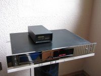
just noticed one very sexy Radiant on German ebay. One button on the front panel is what I was always dreaming about, nothing extra
here is the link
just noticed one very sexy Radiant on German ebay. One button on the front panel is what I was always dreaming about, nothing extra
here is the link
Attachments
I would also consider the audiogd OPA discrete opamps (I think the sun is supposed to be very similar to Burson!)
I can vouch for Audio GD's
Have Earth and Sun models and they are superior to 627's and 49710's ( I have used these too ) in the context of my system.
Don't want to compare or make statements in relation to Burson or the similarities therein ( hahaha ) but I can have an e mail from Kingwa of Audio GD within 6 hours answering my sometimes stupid questions - he's some guy.
What really baffles me is why people pay so much for Bursons...?
Doesn't anyone visit the Audio GD website ?
must admin that Bursons are highly overpriced, though there are many reviews in the net saying how good they are. Perhaps this is one of the reasons why people are ready to pay 10x more just for the name
AndrewGM
where did you use Earth and Sun opams, was it preamp or cd or some other devise?
Asking as I have finally changed old stock opams in Restek's preamp stage to 3x 49710 and noticed the difference immediately (plenty of other mods have been done accordingly too) and as it's the weakest (simplest) point the amp, probably swapping to discrete components like Bursond or Sun/Earth opams could bring even bigger results hence asking
AndrewGM
where did you use Earth and Sun opams, was it preamp or cd or some other devise?
Asking as I have finally changed old stock opams in Restek's preamp stage to 3x 49710 and noticed the difference immediately (plenty of other mods have been done accordingly too) and as it's the weakest (simplest) point the amp, probably swapping to discrete components like Bursond or Sun/Earth opams could bring even bigger results
hence askingHoping you're still watching this thread dtses!
Did you ever check your biasing?
Looking at mine, each output device is running into 0.15r and only passing 1.5mV.
This means the bias is set at approximately 10mV per device. According to the information I've got (Thanks "Thomo", "Fidelity Audio" and the TNT web Pages) this is woefully low. TNT suggest at least 100mA min and 150mA max per device (assuming the heatsinks etc are up to the job). Obviously this is biased more into class A and so the amp will run much hotter and draw more current even at low volume.
Based on this, I've started to increment the bias.
This table is based on 0.15r
1.5mV = 10mA
4 mV = 26.7mA
8 mV = 53.3mA
10mV = 66.7mA
15mV = 100mA
I've set mine to approx 10mV so 66.7mA and wil run it for a few hours to see how it behaves but the initial indication is that it is very dynamic (not that it wasnt before) and eager. We'll see where it goes.
Any subjective opinions on my as usual "cavelier" approach welcome!
The TNT article on biasing is here
Adjusting the Bias Of Your Amp [English]
OK so after a few hours serious listening and I've backed it off a bit down to 7.5mV which should be about 50mA. Running at high volume for an extended period, it got much hotter than I was comfortable with. Although the heatsinks are large, I think they could do with being much larger!!
Listening impressions.....Wow!!!! much more dynamic at lower volumes and an icredible amount of detail in the sound. Placement was extraordinary! I've never heard my system sound like that before!! Awesome attack and just more of everything.
Leaves me with a question.....why was it set so low from the factory??? Is it just to be on the safe side?? seems way off the mark to me...unless I'm missing something??
that seems to be nice and simple improvement, Ian
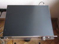
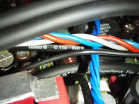
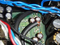
I have replaced old oxidated wires between ALPS pot, pre and power sections with OFC shielded Tasker C114 0.25mm cable. Looks sexy, hope that some audible improvements also appear.
Will try that biasing mod a bit later for sure.
I have replaced old oxidated wires between ALPS pot, pre and power sections with OFC shielded Tasker C114 0.25mm cable. Looks sexy, hope that some audible improvements also appear.
Will try that biasing mod a bit later for sure.
Attachments

cheers!
left channel produce very distorted sound on the preamp output (check by desoldering new replaced wire between pre and power section). What could be the cause?
I didn't turn on the amp for several months after I swapped to Tasker wires. Second opamp (previously was 2 LME49710HA) replaced to OPA2132. No mods since that.
Checked all opams in pre section by replacing with working OPA2132s. All opams are fed with according +- voltage.
What could be the cause? What else could I check?
I couldn't get the Bursons to run in the power stage (the amp stayed in protect mode) but the pair in the pre were a revelation!!
Apparently the current supply in this point of power amp is too low.
You need at least 19mA but 50mA is ideal for Burson. (I guess that 12-25V is available in this area?). Pls look for the resistor which is supplying the current and reduce it accordingly to reach ~ 50mA.
Then you will reach the next level of excellence...
I used sucessfully Burson DualOpAmp in Phonostage of modded Luxman taking care of right "environment" re. V and A.
Hoping you're still watching this thread dtses!
Did you ever check your biasing?
....
This table is based on 0.15r
1.5mV = 10mA
4 mV = 26.7mA
8 mV = 53.3mA
10mV = 66.7mA
15mV = 100mA
I've set mine to approx 10mV so 66.7mA and wil run it for a few hours to see how it behaves but the initial indication is that it is very dynamic (not that it wasnt before) and eager. We'll see where it goes.
Cheers Ian,
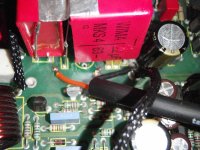
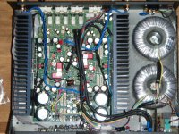
Finally I've got 4 matchig pairs of new old stock genuine Toschiba transistors
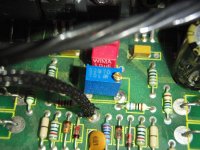
Replaced them yesterday along with 8 x 0.15R power resistors - IRC U.S. 1% placed in parallel. I have also swapped both 1k trimmers to new blue high precision ones to adjust the bias carefully.
So now will play with the values.
Just to confirm, 50mA current is the sum of all 4 resistors per channel, right? Perhaps some additional heatsink would be good if I would like to go further?
Any new mods, btw?
I think I set the volt drop across the resister to give about 50mA but I should really double check. According to my posts I started at 1.5mV per resistor and settled on 7.5mV. That's about 50mA. You could try a bit more if you have lots of ventilation!
Only mods I've done at the moment is to temporarily fit lme49720ha in the preamp instead of the bursons. The reason was that I think the bursons need better regulation to sound best. I've started to build an off board PSU for the preamp and I'll run that into a couple of my regs which will hopefully sort the pre section out once and for all.
Only mods I've done at the moment is to temporarily fit lme49720ha in the preamp instead of the bursons. The reason was that I think the bursons need better regulation to sound best. I've started to build an off board PSU for the preamp and I'll run that into a couple of my regs which will hopefully sort the pre section out once and for all.
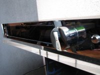
Yesterday I set the bias of about 4.9-5 mV on every power resistor and then had a quick test. Bloody hell, that was something, I was shocked from the very first seconds of Metallica's My world - so much air, the scene was splendid and every instrument was separated as I haven't heard before, especially the drums.
The bad point is that Restek is very hot now even on the low volume, haven't tested it on 11 o'clock as I usually watch movies. I think it would be necessary to add some additional heatsinks on top of existing ones...
Perhaps some aluminium 15x50-70x250mm would help a bit?!
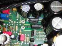
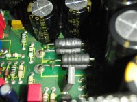
Regarding new genuine Toschiva transistors, I still have some discrepancy between 3 out of 4 pairs, like 4.8mV and 5.4mv or even 4.3 and 5.8mv, though anyway I managed to set every pair to 10mV +-0.1.
Not sure if these changes are the result of biasing or new genuine transistors' affect or adjusting DC offset by replacing 1k pot to multiturn one, nevertheless I'm very happy with the changes will post few pics later.
The bad point is that Restek is very hot now even on the low volume, haven't tested it on 11 o'clock as I usually watch movies. I think it would be necessary to add some additional heatsinks on top of existing ones...
Perhaps some aluminium 15x50-70x250mm would help a bit?!
Regarding new genuine Toschiva transistors, I still have some discrepancy between 3 out of 4 pairs, like 4.8mV and 5.4mv or even 4.3 and 5.8mv, though anyway I managed to set every pair to 10mV +-0.1.
Not sure if these changes are the result of biasing or new genuine transistors' affect or adjusting DC offset by replacing 1k pot to multiturn one, nevertheless I'm very happy with the changes
will post few pics later.as promised, I know everybody likes pics
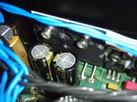
So it's about 5-5.5mV on every transistor now and I get 50 c on the roght heatsink and 46 c on the left with a digital thermometer. A bit confused regarding the difference as all 4 pairs set to equal current or 10.6mV voltage. The amp gets hot after some half of an hour and although thermometer shows only 50 c it's quite hot to hold the heatsink with an arm for more than few seconds. That's with the closed lid. I will add 15-20mm of similar heatsink on top later, hoping to have few more turns of the 1k pot to go for 6-6.6mV.
So it's about 5-5.5mV on every transistor now and I get 50 c on the roght heatsink and 46 c on the left with a digital thermometer. A bit confused regarding the difference as all 4 pairs set to equal current or 10.6mV voltage. The amp gets hot after some half of an hour and although thermometer shows only 50 c it's quite hot to hold the heatsink with an arm for more than few seconds. That's with the closed lid. I will add 15-20mm of similar heatsink on top later, hoping to have few more turns of the 1k pot to go for 6-6.6mV.
Attachments
cheers!
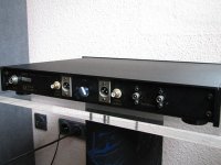
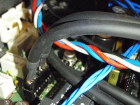
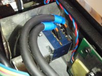
could anyone advice me on connecting step DALE attenuator to the amp please?! This should be a considerable improvement to my mind!
What I want is to completely remove PRE section (10k Alps + opamp buffer + 2 opamps). The thing is that I'm a bit confused with the signal that goes to 22uf cap (ELBIP2) and 2 grounds - GNDA and GND. There is a 2 stranded shielded cable that goes from PRE to the POWER section of each channel. The screen is GND as far a I see from the scheme. Both GNDAs are connected to each other, I assume this should be the ground of my DALE attenuator, shouldn't it?
Attachments
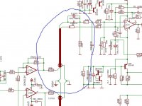
I'd use the single ended input into the power section as you suggest by picking up on the cable that links after the final opamp across into the power section. Are you going to retain the input switching or set it up purely as a power amp? You could take the input to the attenuators from after the switching section before the 1st Opamp??? ;-)
Also I think I know why the burson won't work in the power stage. The Opamp is used to create a balanced signal from the single ended input. It looks like the Opamp works in a strange way with the output fixed meaning the rails will fluctuate instead of the output. Not seen this type of configuration previously. Anyone know what this type of configuration is called??
Also I think I know why the burson won't work in the power stage. The Opamp is used to create a balanced signal from the single ended input. It looks like the Opamp works in a strange way with the output fixed meaning the rails will fluctuate instead of the output. Not seen this type of configuration previously. Anyone know what this type of configuration is called??
hi Ian,
thanks!
The initial idea is to retain switching, change active pre section to LDR thus making the amp an ultimate killer
The other goals are:
-compare pre section with passive DALE attenuator
-compare power section with MyRev FE that I'm about to finish
I believe that's what I need, though not sure how to do that. 1st opamp is a buffer and has 2 inputs - inverting and non inverting, which one do I need to connect to my DALE attenuator?!
Strange that they did not separate pre and power sections like in the Challenger, but it shouldn't be difficult I believe, just asking as don't want to cook anything again
thanks!
The initial idea is to retain switching, change active pre section to LDR thus making the amp an ultimate killer
The other goals are:
-compare pre section with passive DALE attenuator
-compare power section with MyRev FE that I'm about to finish
You could take the input to the attenuators from after the switching section before the 1st Opamp??? ;-)
I believe that's what I need, though not sure how to do that. 1st opamp is a buffer and has 2 inputs - inverting and non inverting, which one do I need to connect to my DALE attenuator?!
Strange that they did not separate pre and power sections like in the Challenger, but it shouldn't be difficult I believe, just asking as don't want to cook anything again
You should be able to trace the input from the relay switching section through to the Opamp. The service manual does not show the full preamp circuit!!! Assuming the Opamp shown in the diagram is the 1st stage after the switching, you need to lift the feeds from before R19 & 20. I would definitely trace the circuit forwards from the output of one of the relays towards the 1st Opamp to double check. Input should end up at the +(non inverting) input. Pins 3 & 5. Remember if you go passive pre, you'll loose the filters that's exist in the active pre section (could be a good or a bad thing!!!)
I'm definitely interested to see how you get on
I'm definitely interested to see how you get on
- Status
- This old topic is closed. If you want to reopen this topic, contact a moderator using the "Report Post" button.
- Home
- Amplifiers
- Solid State
- Restek Fantasy amp cap upgrade + opamps and Bursons!