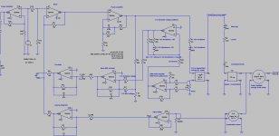
Here is a LTspiceIV simulation of a closed box loudspeaker combining :
- Acceleration FeedBack (AFB) using a piezo sensor from 20 Hz to 120 Hz
- Velocity FeedBack (VFB) using the voice coil as microphone (back EMF extraction) from 120 Hz to 2 kHz
From 20 Hz to 120 Hz, all distorsions caused by large excursions (suspension non linearities and magnetics non linearities) are significantly reduced by the Acceleration FeedBack, using the piezo sensor. In this frequency range, the Acceleration FeedBack also linearized the acoustic response by cancelling the natural resonance of the driver in the closed box enclosure.
From 120 Hz to 2 kHz, the acoustic signature doesn't depend from the piezo sensor. From 120 Hz to 2 kHz, the acoustic signature only depends from the magnetics of the speaker driver, with the coil being used as a giant microphone. In this frequency band, the excursions are small, making the system linear. The amount of Velocity FeedBack has been setup for knocking down the acoustic response by approx 12 dB. The precision is thus about 4 times better than the equivalent system in open loop.
This combination of feedbacks is the result of analysing and modelling :
the Philips Motional Feedback (MFB) system :
Philips Motional Feedback (MFB) - diyAudio
and
the Korn-Macway "Servo Sound" system :
Servo-Sound made in Belgium - diyAudio
See attached files.
Cheers,
Steph
Attachments
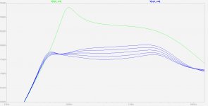
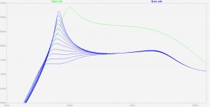
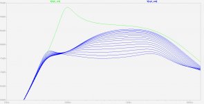
Nothing new. Here are two variants showing the frequency domain of the acceleration feedback and the freqency domain of the velocity feedback.
See attached files
Steph
See attached files
Steph
Attachments
Last edited:
I seem to recall a thread round here somewhere...
Dude was abusing a toy radar gun for similar purpose.
But have you seen those plastic strips with an optical
gradient? Either counting stripes as they whiz by, or
perhaps just measuring a shade of grey, or both?
Might be the makings for a neat servo. Wonder if an
optical mouse could do it? Nah, probably too slow...
Or maybe have a piezo emit some ultrasonic chirp?
Maybe you could read that back as Doppler shift?
Again, maybe thats too slow.. I dunno. Maybe slow
wouldn't matter, if the system could learn and map
out the necessary pre-emptive corrections?
Or if you shoot a laser pointer at the cone sideways,
the lit spot would move in and out as the cone moves
forward and back... I don't know how you follow the
moving spot to read the position? I've seen cats try,
their effectiveness is questionable...
Last edited:
or embedding interleaved piezo elements into the membrane :
- a grid of 256 piezo sensors covering the membrane surface able to sensor the membrane acceleration on 256 different points, this should enable identifying the global acceleration plus the cone break-up pattern
- a grid of 256 push-pull piezo actuators (actually, 512 actuators) covering the membrane surface able to dynamically inject a localized mechanical tension on the membrane surface for counteracting membrane break-up
Say you need to manage 512 channels (256 sensors plus 256 push-pull actuators), in analog (processing delays are forbidden). Plus the need to identify and correct membrane break-up. Surely you need digital processing over there (processing matrixes) for setting-up the 256 analog feedback channels in phase and in amplitude. The 256 individual analog straightening signals are certainly not going to be linear, as nearly the same straightening must be applied for a positive excursion, and a negative excursion. Kind of absolute value signal with a round edge for avoiding the zero 1st order discontinuity.
This may be quite interesting ...
How would you organize this ?
Kind of Hubble telescope mirror management, not in aerospace but in a loudspeaker, and not at 0.1 Hz but at 1,000 Hz.
Don't know if LTspiceIV is able to process data in the form of matrixes.
Cheers,
Steph
- Status
- Not open for further replies.