I have several times expressed that I like the Toshiba 2SK3497/2SJ618 power mosfets that, although they're not that new, haven't been used much and especially not in DIY, partly because nobody seems to stock them....
So finally I received my 100 pairs from Digikey, although it took a long time to get them.
My main interest is using them without global feedback so I'm concentrating on measuring how linear they are, also at high frequencies, what the output impedance will be and how fast they are.
I have an amplifier breadboard testbench with exchangeable output stages and have done some measurement to find out how good they are. To have something to compare with I have done the same measurements with the best Bipolars (OnSemi NJW3281/NJW1302 with KSC2690/KSA1220 drivers) and Hitachi style lateral mosfets (Semelab BUZ900/BUZ905).
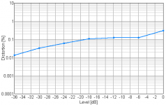
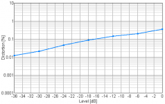
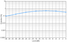
All measurements are done with a fast jfet input folded cascode voltage amplifier with an output impedance of 3.4 Kohm, with no global feedback, and with a single set of output devices. 0db reference is at 17V RMS into 8 ohm, 1 db below clipping of the driver stage.
First are the Bipolars, looks pretty good with THD at 0.3% and quickly going down at lower levels, with an output impedance of 0.4 ohm and power bandwidth of 900 Khz. I have used 0.22R emitter resistors, so half the output impedance are from those. You can expect results to be consistent when paralleling more output pairs, which will result in lower output impedance. Bias is set at 100 mA, and higher will improve lower level performance, keeping them in class A further up.
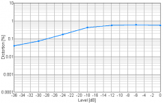
Next is the Hitachi style mosfets, THD is significant higher, close to 1%, but most of it is 2nd harmonic. Output impedance is 1.2 ohm, with 0.1R source resistors. Paralleling more pairs will really help, both on output impedance and THD as they are due to the unlinear and low Yfs. Bias is set at 100 mA and higher will improve significant on performance and the working point moves closet to their linear operating point, sweet spot is probably 3-5 pairs and 200 mA bias per pair. Without current drivers the power bandwidth is 180 Khz, and THD increases at higher frequencies, but not that much. Cgs is dominant over Cgd so paralleling more will not change the high frequency performance that much, with a little higher drive current in the voltage amplifier they will work fine without extra current drivers.
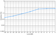
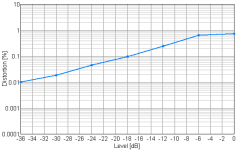
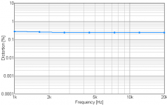
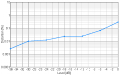
And now the Toshiba power mosfets. THD with 100 mA bias don't look to good but are mostly 2nd harmonic. Output impedance is 0.35 ohm with 0.1R source resistors, close to the Bipolars thanks to their high Yfs. But with higher bias they really shine, 300 mA get them into the linear range and now they look very good. But power bandwidth is only 132 Khz and THD increases with frequency, reaching 1% at 20 Khz. As Cgd is dominant over Cgs then paralleling more pairs will just make it worse. A single pair could be used with higher drive current, but a current driver stage is really needed for good results, then the power bandwidth goes up to 730 Khz and THD don't raise with frequency. With a current driver stage you can also lower current in the voltage amplifier stage, ending with THD <0.2% at 1 db below full power.
My conclusion are that the Toshiba power mosfets could be a good fit to make a great non feedback amplifer, assuming a current driver stage and 300 mA bias per pair.
The bipolar are also good, and have the advantage that you don't need to match them when paralleling, unlike the mosfets.
The Hitachi style laterals mosfets really needs to be used in amplifiers with feedback.
The names of the attached THD curves should explain what they are, but basically they follow the text.
Soren
So finally I received my 100 pairs from Digikey, although it took a long time to get them.
My main interest is using them without global feedback so I'm concentrating on measuring how linear they are, also at high frequencies, what the output impedance will be and how fast they are.
I have an amplifier breadboard testbench with exchangeable output stages and have done some measurement to find out how good they are. To have something to compare with I have done the same measurements with the best Bipolars (OnSemi NJW3281/NJW1302 with KSC2690/KSA1220 drivers) and Hitachi style lateral mosfets (Semelab BUZ900/BUZ905).
All measurements are done with a fast jfet input folded cascode voltage amplifier with an output impedance of 3.4 Kohm, with no global feedback, and with a single set of output devices. 0db reference is at 17V RMS into 8 ohm, 1 db below clipping of the driver stage.
First are the Bipolars, looks pretty good with THD at 0.3% and quickly going down at lower levels, with an output impedance of 0.4 ohm and power bandwidth of 900 Khz. I have used 0.22R emitter resistors, so half the output impedance are from those. You can expect results to be consistent when paralleling more output pairs, which will result in lower output impedance. Bias is set at 100 mA, and higher will improve lower level performance, keeping them in class A further up.
Next is the Hitachi style mosfets, THD is significant higher, close to 1%, but most of it is 2nd harmonic. Output impedance is 1.2 ohm, with 0.1R source resistors. Paralleling more pairs will really help, both on output impedance and THD as they are due to the unlinear and low Yfs. Bias is set at 100 mA and higher will improve significant on performance and the working point moves closet to their linear operating point, sweet spot is probably 3-5 pairs and 200 mA bias per pair. Without current drivers the power bandwidth is 180 Khz, and THD increases at higher frequencies, but not that much. Cgs is dominant over Cgd so paralleling more will not change the high frequency performance that much, with a little higher drive current in the voltage amplifier they will work fine without extra current drivers.
And now the Toshiba power mosfets. THD with 100 mA bias don't look to good but are mostly 2nd harmonic. Output impedance is 0.35 ohm with 0.1R source resistors, close to the Bipolars thanks to their high Yfs. But with higher bias they really shine, 300 mA get them into the linear range and now they look very good. But power bandwidth is only 132 Khz and THD increases with frequency, reaching 1% at 20 Khz. As Cgd is dominant over Cgs then paralleling more pairs will just make it worse. A single pair could be used with higher drive current, but a current driver stage is really needed for good results, then the power bandwidth goes up to 730 Khz and THD don't raise with frequency. With a current driver stage you can also lower current in the voltage amplifier stage, ending with THD <0.2% at 1 db below full power.
My conclusion are that the Toshiba power mosfets could be a good fit to make a great non feedback amplifer, assuming a current driver stage and 300 mA bias per pair.
The bipolar are also good, and have the advantage that you don't need to match them when paralleling, unlike the mosfets.
The Hitachi style laterals mosfets really needs to be used in amplifiers with feedback.
The names of the attached THD curves should explain what they are, but basically they follow the text.
Soren
Attachments
-
 17Vrms_Bipolar_100mA_8R.png4.6 KB · Views: 3,250
 -
 17Vrms_Hitachi_100mA_8R.png4.6 KB · Views: 3,166
 -
 17Vrms_Hitachi_200mA_8R.png4.7 KB · Views: 3,128
 -
 17Vrms_Hitachi_300mA_8R.png4.8 KB · Views: 3,143
 -
 17Vrms_Toshiba_300mA_8R.png4.7 KB · Views: 416
 -
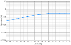 17Vrms_Toshiba_200mA_8R.png4.6 KB · Views: 411
 -
 17Vrms_Toshiba_100mA_8R.png4.5 KB · Views: 3,108
 -
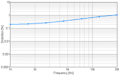 17Vrms_Toshiba_100mA_8R_Freq.png4.2 KB · Views: 433
 -
 17Vrms_Toshiba_100mA_Driver_8R_Freq.png4 KB · Views: 552
 -
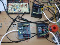 Test_Setup.jpg619 KB · Views: 1,149
Last edited:
just for completeness, what was distortion readings and bandwidth without an output stage attached (i.e. the driver alone)?
-3db Power Bandwidth without output module and just the 3.4K load is about 1 Mhz, but there might be some extra capacitance due to the breadboard design....
THD versus Power, again with 0db at 17V rms. All test were run with +- 30V from my lab power supply.
Attachments
are there p-spice parameters online?
Not that I know of, but I haven't looked that much, prefer to play with actual hardware
")
Soren
Toshiba send me "Level 3" p-spice parametersNot that I know of, but I haven't looked that much, prefer to play with actual hardware
Soren
Attachments
Hello, I have an amplifier self-made 20 years ago Hybrid Tubes mosfet zero feedback, and use three pairs of MOSFET 2SJ162 and 2SK1058. I would like to replace them with better and modern mosfet, best sounding. The 2SJ162 and 2SK1058 are driven by J79 K216 mosfet to220. Thanks for your suggestions.
why?
more specifically, what are you trying to improve?
if you change devices, are you willing to also rebuild the biasing and the frequency compensation, make design changes or adjustments for potentially different drive requirements, etc.?
i could guess it might be a more beneficial activity to try to add error correction to the output stage.
also still not a trivial task, but i think more "bang" for the intellectual buck.
mlloyd1
- Status
- This old topic is closed. If you want to reopen this topic, contact a moderator using the "Report Post" button.
- Home
- Amplifiers
- Solid State
- Toshiba Power Mosfets 2SK3497/2SJ618 - A little testing