And what about try this my design ? It have Hawksford/Cordell error correction, 120W into eight, 170W into four... Practical design you can see here http://www.diyaudio.com/forums/solid-state/152945-pavel-dudeks-upupa-epops-amplifiers-ii-24.html ...
And what about try this my design ? It have Hawksford/Cordell error correction, 120W into eight, 170W into four... Practical design you can see here http://www.diyaudio.com/forums/solid-state/152945-pavel-dudeks-upupa-epops-amplifiers-ii-24.html ...
Are you still using those lateral mosfets with the design, whish i could lay my hands on some.
To bear:
Just found some schematics on Borbely's Amps. I have to agree, a damn nice design particularly the Symmetrical Cascode Input cirquit! So far they are the best Home built projects and kits I have seen") But the schematics on Borbely's website are without values! Does a Part list exist somewhere on the net or did anybody built some kits and still has a Part list! Would be worth checking out first if some of those input transistors are still available.
But the schematics on Borbely's website are without values! Does a Part list exist somewhere on the net or did anybody built some kits and still has a Part list! Would be worth checking out first if some of those input transistors are still available.
Just found some schematics on Borbely's Amps. I have to agree, a damn nice design particularly the Symmetrical Cascode Input cirquit! So far they are the best Home built projects and kits I have seen
But the schematics on Borbely's website are without values! Does a Part list exist somewhere on the net or did anybody built some kits and still has a Part list! Would be worth checking out first if some of those input transistors are still available.2x 2SJ50 & 2x 2SK135
I bought 2 sentec acm-1 mono blocks this weekend and they sound great!! They use 2x 2SJ50 & 2x 2SK135
Sentec-förstärkare, broschyrer mm
http://www.svalander.se/shoppen/pdf/ACM1/schema_acm1.pdf
I bought 2 sentec acm-1 mono blocks this weekend and they sound great!! They use 2x 2SJ50 & 2x 2SK135
Sentec-förstärkare, broschyrer mm
http://www.svalander.se/shoppen/pdf/ACM1/schema_acm1.pdf
Crescendo not bad after all
I built a set of 4 of these. I thought they were rather good. Of course, as they are capable of high frequency, the layout is important.
I have the original articles somewhere. I seem to remember one of the main objectives was to eliminate the Miller capacitor...
You're welcome.
Yes, you're right, if you follow the link to the forum post, one of them is the crescendo (the bottom picture posted) and the other is the mini-crescendo (the top picture posted) with 140 and 70 watt outputs respectively.
I do remember as I was looking round for the schematics, there was a mention about the amp not being very stable and not even a particularly good amp anyway but that's not to say that you could try building one
I built a set of 4 of these. I thought they were rather good. Of course, as they are capable of high frequency, the layout is important.
I have the original articles somewhere. I seem to remember one of the main objectives was to eliminate the Miller capacitor...
Ask someone for Randy Slone's older version of the OptiMOS amp. You could lower the voltage and have a single output pair or run them in parallel for the published rails. They sound very good.
Though I haven't personally tried it yet, Mooly's amp should perfectly fit the bill.
Though I haven't personally tried it yet, Mooly's amp should perfectly fit the bill.
you can lay your hands on some!
Lateral Mosfet
Are you still using those lateral mosfets with the design, whish i could lay my hands on some.
Lateral Mosfet
Hi to all,
I'm presently building this hitachi1977 amp. I found that theae pairs work d669/b649 & mje340/350. I'd hand-drawn the PCB artwork & used enchant. I was surprised how easy it is!
I'd done some modifications with this topology but I've not yet done the PCB artwork. I'm showing the basic circuit to my friends to show how easy it is to build one's amp.
Tank to all!
2sj50/2sk135 all-fet amp.
hello
i found this schematic searching for a small amp around 50/75W/8ohm to build with my small bag of j50/k135.
Someone can read japanese or know about this circuit? i'm not expert to judge it, seems class A?
I can't understand the function of the upper switch close to led.
Saluti
hello
i found this schematic searching for a small amp around 50/75W/8ohm to build with my small bag of j50/k135.
Someone can read japanese or know about this circuit? i'm not expert to judge it, seems class A?
I can't understand the function of the upper switch close to led.
Saluti
Attachments
dear sir ,
i have heard that some mosfet are available in india at khandelwal electronics,can any body give me the shop number,at lajpar market.my email is alvi.masood251@gmail.com
i have heard that some mosfet are available in india at khandelwal electronics,can any body give me the shop number,at lajpar market.my email is alvi.masood251@gmail.com
Lots of good and bad was said about the Elektor Crescendo amplifier of the 80's.I know that it suffered from oscillation problems. I have built a few over the years for friends and myself. These amplifiers are used in my home audio sytems, with a few modifications over the years with good results,and i can assure anyone who wants to build them to go ahead with the project.The modifications that i did will result in a complete stable amplfier which will beat the pants off any mosfet design past and present.THE SOUND IS POWERFUL WITH TRMENDEOUS BASS AND CLEAR HIGHS WITH NO DISTORTIONS AT HIGH VOLUME.Highly recommended. Fell free to contact me and i will detail the modifications.
Lots of good and bad was said about the Elektor Crescendo amplifier of the 80's.I know that it suffered from oscillation problems. I have built a few over the years for friends and myself. These amplifiers are used in my home audio sytems, with a few modifications over the years with good results,and i can assure anyone who wants to build them to go ahead with the project.The modifications that i did will result in a complete stable amplfier which will beat the pants off any mosfet design past and present.THE SOUND IS POWERFUL WITH TRMENDEOUS BASS AND CLEAR HIGHS WITH NO DISTORTIONS AT HIGH VOLUME.Highly recommended. Fell free to contact me and i will detail the modifications.
Hi SUZTEK,
I sent you PM, can you send me details?
Thanks
dear sir,
thanking you for for sendig precious advice for crescendo amplifier.
give me suggestion.
There s no big secret , and i wonder why the guy dont speak
about it in this forum..
The crescendo has no frequency compensation , or rather , the designer
rely on the lateral fets input capacitance to load the VAS and thus
provide a kind of shunt compensation.
This scheme is somewhat tricky most of the time , so adding
two compensations caps of about 27pF is the main and perhaps
only cure to make this amp stable and functionnal.
In the Crescendo schematic below , these are C2 and C3.
Attachments
Last edited:
.jpg")

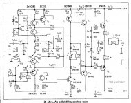
I'm resurrecting this old thread. Here in Hungary we also have a version for these nice FETs, this circuit is capable of 20 W at 8 Ohm. The schematic made by Piret Endre is based on a complementer-symmetric topology made with BJTs, and implemented to accomodate these laterals. The main problem was the harsh, metallic "FET-sound", with high level of harmonics generated by the feedback loop's impact. So the main solution was to divide the feedback between two stages (30 dB global and 18 dB after the first stage of the cascode).
R32 is chosen as zero, compensating the higher Rchannel resistance of P type device.
It is a very nice sounding unit (during construction, the constructor improved with the help of "critical ears" having no influence from design but more from what they hear). It is stable and capable of driving hard to drive loads.
The used semiconductors are the typically available devices in Hungary in the 80's, and the constructor states it can be scaled to greater power, but T7 and T8 is a limiting factor since the Vce value of those transistors are only 65 V.
I'm going to upgrade this design to make it capable for around +-50-70 V and maybe include another pair of these FETs-if required.
Attachments
- Status
- This old topic is closed. If you want to reopen this topic, contact a moderator using the "Report Post" button.
- Home
- Amplifiers
- Solid State
- Amp circuit with 2SJ50 & 2SK135