joensd said:I always wanted to try that project (like many others) but still haven´t tried. The PCB layout is really nice with the possibility of adding Alps and Panasonic with (or without) motor.
If you want the layout I think I still have it in pdf-format.
Jens
By chance do you have a copy of the layout?
Just need your email-adress.By chance do you have a copy of the layout?
It is a simple opamp preamplifier in fact.Also, I'd be very interested to see the elektor servo control circuit, if you have it to post?
I have the article in pdf-format so I can´t post it here.
(at least not easily)
I´ve seen a lot of Elektor circuits on this site but aren´t they copyrighted as well?
Regards
Jens
Hey Jens,
I'm not sure of the copyright issues with elector articles. I would like a copy of the pdf but I'm really prefer to avoid posting my email address on a public forum I've tried sending my address to you through the message channel but you've got it turned off
  Perhaps you can post the PDF, or message me with your email?
I'm not sure of the copyright issues with elector articles. I would like a copy of the pdf but I'm really prefer to avoid posting my email address on a public forum
I've tried sending my address to you through the message channel but you've got it turned off Perhaps you can post the PDF, or message me with your email? Re: pleeez
Uli, I have dug out the schematic (2 sheets), had them scanned. The original files were made with OrCAD SDT IV, which ran under DOS, so I can't recreate the files electronically. They scanned sheets are too large to post. Maybe you can copy the diagrams into your favorite CAD program and post that for the others?
Jan Didden
uli said:
Hi Jan,
YES there IS interest!

Uli
Uli, I have dug out the schematic (2 sheets), had them scanned. The original files were made with OrCAD SDT IV, which ran under DOS, so I can't recreate the files electronically. They scanned sheets are too large to post. Maybe you can copy the diagrams into your favorite CAD program and post that for the others?
Jan Didden
Re: pleeez
There is a PIC microcontroller that receives & decodes standard RC5 commands. It drives the potmeter, source select (3 sources) and mute. I also have a diagram on a DIY RC5 transmitter for this.
At power-on, it mutes the system and drives the volume down for 12 secs to be sure that it is at zero. (The ALPS moterpot has a full travel time of 12 +/- 3 secs). Then unmutes and increases the power for 2 secs to start at low volume. The OFF command switches the preamp to mute, but remembers the last selected source for next ON command as long as the mains stays on (which should be always). I will send the scanned diagrams to Uli.
Jan Didden
uli said:
Hi Jan,
YES there IS interest!
Uli
supernet said:Jan, do you use separate IR remote controler for Alps pot and please post the schematic.
Thanks
There is a PIC microcontroller that receives & decodes standard RC5 commands. It drives the potmeter, source select (3 sources) and mute. I also have a diagram on a DIY RC5 transmitter for this.
At power-on, it mutes the system and drives the volume down for 12 secs to be sure that it is at zero. (The ALPS moterpot has a full travel time of 12 +/- 3 secs). Then unmutes and increases the power for 2 secs to start at low volume. The OFF command switches the preamp to mute, but remembers the last selected source for next ON command as long as the mains stays on (which should be always). I will send the scanned diagrams to Uli.
Jan Didden
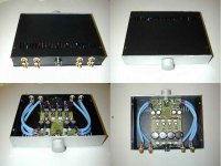
The first post asked if anybody had built it. I am happy to say that today the answer is yes. I am building an Aleph P but my PCBs are taking forever for me to finish. So, I built this one while waiting for myself. Seems to work perfectly. Resistors are Welwyn RC55Y and pot is Vishay/Sfernice P11. Local bypass is RIFA MMK. Sound is so far great and I'll use with my GCs mono blocks as my second system. PSU is 4 individual LM317 with adjust bypassing and a 10.000 uF filter cap each and then 47 uH plus 1200 uF Panasonic FC caps. This gives true mono build as PCB is galvanically separated sides. The transformer is in a separate box connected via 4 twisted pairs umbillical cord. Internal wiring is Supra EFF-1.
Attachments
 I must search those now....
Preamp
Hi,
I have built the circuit omitting the first opamp and adding a simple push-pull outputstage taken from Walt Jungs book "Audio OP-Amp Applications". I have built the circuit on a small circuit card that fitted the Mark-Levinson JC-2 or ML-1 preamplifier with protruding pins. To replace defective line-modules.
Later I went completely discrete resulting in better sound but much greater complexety not fitting in the tight space of the ML preamp.
The opamp choice is very critical:
OPA 627 performs very well here, but also AD823 or AD744. It is all a matter of taste. With the AD744 sound was remarkably similar to the original modules.
Me too! (toooo many pics, sorry)
Hi all,
I've been lurking this thread for some time. Ok, it is not very active, but anyways. I felt that I should report on my "progress".
It all started out when I heard UrSv's preamp, and I needed a new project. Also, my steaph father has his 50'th birthday in a couple of weeks so I thought; "what the heck, the old man need some new headphones and an amp for it as well".
So that was the start of my project...
I tried the concept on a small PCB, just to see if I could get it working, which indeed is not really hard with this curcuit. When I started the design of the card I really didn't know what kind of PS I would use, but I resolved that later. First thing first...
Here is the prototype I made, before populating it:
When the board was populated, ofcourse I needed a powersupply, and since I found a 2x15V transformer in my scrap box, a handful of IRF540 and IRF9620 FET's, as well as some 9.1V zener diodes, the choice was not hard to make. A simple voltage regulator (a la the one you find in the Aleph P manual). The 18.2V over the zeners, dropped by some 3.something volts over the FET's (in my case, lucky guy) gave me +/- 15 volt. First try it on a bread board here:
Together with the prototype, it looked like this:
But as I said (actually I wrote it just above...) the old man deserves a nice headphone amp. I accidentally went to the local electronics market (MediaMarkt) and all by a sudden, I had 245 CHF less in my pocket, and a box of AKG K271 Studio Headphones in my hands. This was a perfect opportunity to tweak this circuit. Ok, not too much tweaking, but hey... What I did to the circuit was this:
An open loop BUF634P, just hanged on there. This worked pretty well. I breadboarded the whole thing and there seemed to be enough "power" to drive the headphones. Boy, now I almost don't want to give this stuff away...
So I started putting it all on one board. Two "mono channels", with a PS each. It took a few hours before I was happy with the layout, but finally I got it...
Tooooo the wooork bench... (or just to the kitchen, with a quick break in the hallway).
Here is UrSv shining some light onto my PCB. We use a standard 100W lightbulb. Ok, it takes about 18 minutes to get a proper card lit, but we had plenty of time.
So, finally I started using the heavy artillery in my kitchen. For a while I was a bit confused which bottle to fill up my wisky glass from, but I think I got it now. Yellowish goes into the glass, the greenish goes into the plastic bucket for etching... For developing the photoresist I use plain water and sink-o-rinsing (caustic soda). To develop myself I used a single malt from a Scottish island.
After this, it was too late to do any drilling (I live in a housing complex, with NEIGHBOURS... damn them, lazy bastards who go to bed AT 22.00!!!). Rest for the night...
Here is a picture of my provisional working area in my kitchen. As long as I stay single (as the malt), I am allowed to do so. DO NOT TRY THIS IF YOU ARE NOT SINGLE, trust me, I've not always been single.
At this stage (see pic below) I kind of started thinking... Shouldn't I have space for three resistors each next to the diodes... Here is only space for two... What the heck...
Ofcourse I had missed out the extra resistor... I had to cut traces on the PCB at four places and "patch" the curcuit a bit.
No worries... After this, I decided to try one channel's PS with the prototype pre amp PCB, before proceeding.
And with the prototype:
It worked well! I decided to do the whole thing. It is amazing how long time it takes to do all this. Time really flies when you have fun. Luckily. UrSv was easily pursued into coming over to cook for me (also he could use my washing machine, since he slept too long to use the one in his house). Carbonara! Holy cow, if you ever want to eat good carbonara, invite UrSv to your place!
Almost at the same time as the food was served, I finished populating the board. Now it is time to thank Nelson again.
(Sidenote: What does nelson have to do with the Elektor Preamp, you might ask yourself... He does, quite a lot! At least in my case... His work kind of inspired me quite a lot this year (and the year before), and I looked into most of the designes he published on his webpages. The PS is a rip directly from the Aleph P manual. I took the regulating circuit (which is kind of a text book example on how to do it, but I learned from the Aleph P manual, ok), which is a positive voltage regulator. I mirrored the whole thing, putting on a FET with the other polarity, and I got the negative feed, so... THANK YOU NELSON PASS! I owe you for this one!)
And since I as of now don't have a box for the amp, I just rigged it on top of my LD player (yes LD, like in Laser Disk) and hooked it up to my Aleph 30 (again, thank you...). And there was sound!
And, as a tribute to the Aleph series... Yes, it is... Blue!
As for sound and everything, I refer to UrSv. All he says about the sound, circuit and all, I agree. The most important is that I now have a nice gift for the old guy. This amp will drive the AKG head phones, and the Leach Amp I put in the listening room a year ago.
See you!
//magnus
Hi all,
I've been lurking this thread for some time. Ok, it is not very active, but anyways. I felt that I should report on my "progress".
It all started out when I heard UrSv's preamp, and I needed a new project. Also, my steaph father has his 50'th birthday in a couple of weeks so I thought; "what the heck, the old man need some new headphones and an amp for it as well".
So that was the start of my project...
I tried the concept on a small PCB, just to see if I could get it working, which indeed is not really hard with this curcuit. When I started the design of the card I really didn't know what kind of PS I would use, but I resolved that later. First thing first...
Here is the prototype I made, before populating it:
An externally hosted image should be here but it was not working when we last tested it.
When the board was populated, ofcourse I needed a powersupply, and since I found a 2x15V transformer in my scrap box, a handful of IRF540 and IRF9620 FET's, as well as some 9.1V zener diodes, the choice was not hard to make. A simple voltage regulator (a la the one you find in the Aleph P manual). The 18.2V over the zeners, dropped by some 3.something volts over the FET's (in my case, lucky guy) gave me +/- 15 volt. First try it on a bread board here:
An externally hosted image should be here but it was not working when we last tested it.
Together with the prototype, it looked like this:
An externally hosted image should be here but it was not working when we last tested it.
But as I said (actually I wrote it just above...) the old man deserves a nice headphone amp. I accidentally went to the local electronics market (MediaMarkt) and all by a sudden, I had 245 CHF less in my pocket, and a box of AKG K271 Studio Headphones in my hands. This was a perfect opportunity to tweak this circuit. Ok, not too much tweaking, but hey... What I did to the circuit was this:
An externally hosted image should be here but it was not working when we last tested it.
An open loop BUF634P, just hanged on there. This worked pretty well. I breadboarded the whole thing and there seemed to be enough "power" to drive the headphones. Boy, now I almost don't want to give this stuff away...
So I started putting it all on one board. Two "mono channels", with a PS each. It took a few hours before I was happy with the layout, but finally I got it...
Tooooo the wooork bench... (or just to the kitchen, with a quick break in the hallway).
Here is UrSv shining some light onto my PCB. We use a standard 100W lightbulb. Ok, it takes about 18 minutes to get a proper card lit, but we had plenty of time.
An externally hosted image should be here but it was not working when we last tested it.
So, finally I started using the heavy artillery in my kitchen. For a while I was a bit confused which bottle to fill up my wisky glass from, but I think I got it now. Yellowish goes into the glass, the greenish goes into the plastic bucket for etching... For developing the photoresist I use plain water and sink-o-rinsing (caustic soda). To develop myself I used a single malt from a Scottish island.
An externally hosted image should be here but it was not working when we last tested it.
After this, it was too late to do any drilling (I live in a housing complex, with NEIGHBOURS... damn them, lazy bastards who go to bed AT 22.00!!!). Rest for the night...
Here is a picture of my provisional working area in my kitchen. As long as I stay single (as the malt), I am allowed to do so. DO NOT TRY THIS IF YOU ARE NOT SINGLE, trust me, I've not always been single.
An externally hosted image should be here but it was not working when we last tested it.
At this stage (see pic below) I kind of started thinking... Shouldn't I have space for three resistors each next to the diodes... Here is only space for two... What the heck...
An externally hosted image should be here but it was not working when we last tested it.
Ofcourse I had missed out the extra resistor... I had to cut traces on the PCB at four places and "patch" the curcuit a bit.
An externally hosted image should be here but it was not working when we last tested it.
No worries... After this, I decided to try one channel's PS with the prototype pre amp PCB, before proceeding.
An externally hosted image should be here but it was not working when we last tested it.
And with the prototype:
An externally hosted image should be here but it was not working when we last tested it.
It worked well! I decided to do the whole thing. It is amazing how long time it takes to do all this. Time really flies when you have fun. Luckily. UrSv was easily pursued into coming over to cook for me (also he could use my washing machine, since he slept too long to use the one in his house). Carbonara! Holy cow, if you ever want to eat good carbonara, invite UrSv to your place!
An externally hosted image should be here but it was not working when we last tested it.
Almost at the same time as the food was served, I finished populating the board. Now it is time to thank Nelson again.
(Sidenote: What does nelson have to do with the Elektor Preamp, you might ask yourself... He does, quite a lot! At least in my case... His work kind of inspired me quite a lot this year (and the year before), and I looked into most of the designes he published on his webpages. The PS is a rip directly from the Aleph P manual. I took the regulating circuit (which is kind of a text book example on how to do it, but I learned from the Aleph P manual, ok), which is a positive voltage regulator. I mirrored the whole thing, putting on a FET with the other polarity, and I got the negative feed, so... THANK YOU NELSON PASS! I owe you for this one!)
An externally hosted image should be here but it was not working when we last tested it.
And since I as of now don't have a box for the amp, I just rigged it on top of my LD player (yes LD, like in Laser Disk) and hooked it up to my Aleph 30 (again, thank you...). And there was sound!
An externally hosted image should be here but it was not working when we last tested it.
And, as a tribute to the Aleph series... Yes, it is... Blue!
An externally hosted image should be here but it was not working when we last tested it.
As for sound and everything, I refer to UrSv. All he says about the sound, circuit and all, I agree. The most important is that I now have a nice gift for the old guy. This amp will drive the AKG head phones, and the Leach Amp I put in the listening room a year ago.
An externally hosted image should be here but it was not working when we last tested it.
See you!
//magnus
Disclaimer
... the book (with the semi nude picture) behind me and UrSv on the kitchen pics, is a biography on a French girl and how/why she became a "star" in the adult industry. It is not porn, really... There are other books like it from e.g. Linda Lovelace (which is pretty sad reading), and Tracy Lords (also sad reading about her younger days, though she seems to work things out nowdays). Don't ask me why I read them all. I read a LOT, not only these (very interesting) books
Just thought of explaining that before anyone start jumping me on the issue.
//magnus
Sweet. Looks even better in real life.
As always I am fascinated to see an audio set-up working and sounding good in this genuine Stilleben fashion which swede masters so well. Everything mounted and suspended around curtains and hanging by the cables using professional Sony CD changers as a table. Everything spiced up with lots of alligator clips.
Now what about a box?
Disclaimer: Do NOT try and eat as much Carbonara as seen in the picture. It could hurt you.
BTW: Even if I look drunk on the picture I'm not.
NB: Should any of y'all like the blue PCBs as much as I do then Conrad sells them in Europe. "Original Bungard PCB Blue".
Swede,
May off topic but, I'm not an expert on PCB production.
The way you do looks interesting to me.
What I understand is that you use a standard 100 W light bulb.
Can you please advise:
- Do you use a standard glass plate as well?
- What is the distance from the PCB to the light bulb?
- The exposure time of 18 minutes, how critical is it.
- What PCB material do you use? Is the exposure time dependant upon the brand?
Thank you!
Preamp
To SWEDE : much more better is connect BUF 634 to the feedback loop of opamp, you get much lower distortion, but you must cut off ultrahigh frequencys ( over cca 1 MHz ) by capacitor connected directly from output of opamp and - input and by passive input filter ( on + input ).
To SWEDE : much more better is connect BUF 634 to the feedback loop of opamp, you get much lower distortion, but you must cut off ultrahigh frequencys ( over cca 1 MHz ) by capacitor connected directly from output of opamp and - input and by passive input filter ( on + input ).
- Status
- This old topic is closed. If you want to reopen this topic, contact a moderator using the "Report Post" button.
- Home
- Amplifiers
- Solid State
- Have anybody built this active pot from Elektor?