hello,
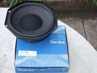
I have a couple NOS Philips AD 7066/MFB speakers lying around. Can somebody advise the best way using them, nowadays ?
- In 2010, are we still forced to use them in a closed-box arrangement ? Can't we design something demanding less cone excursion in the deep bass range like a 4th order bass-reflex or a 4th order dual-chamber ?
- How would you wire the system using a symmetric d'Appolito configuration, using two such AD 7066-MFB drivers ? How would you blend the two accelerometers signals for using one common amplifier ?
- What to do for preserving or enhancing some supposed features like the MFB "eating" the listening room resonance modes ?
Regards,
Steph
Attachments
Long time ago, there was a design idea published in Elektor about transforming any existing loudspeaker driver into a MFB one.
The idea consisted of glueing a 20mm piezo transducer on top of the voice coil, under the dust cap. Epoxy glue to be used for straightening the dust cap.
The piezo voltage was then buffered by a TL071 used as unity gain buffer, with a 22 meg ohm input resistance for ensuring a decent DC path for the TL071 input stage. This way you could get a 100mV MFB signal down to 5Hz. The 22 meg ohm combining with the equivalent piezo capacitance is the cause of the 5Hz high-pass response.
Can anybody report about this approach ?
Can anybody advise smaller piezo transducers, like 5mm diameter or so, having a much higher mechanical resonance frequency ?
Steph
Last edited:
If you remove the dust cap of a MFB driver, you'll see that the Philips piezo element is very small, and that it is mechanically low-pass filtered using rubber. I guess that after 20 years, this rubber may become hard (higher low-pass frequency), and/or the fixation of the piezo crystal may become lose (increased distorsion).
Can anybody report about such possible aging effects in Philips MFB loudspeakers ?
Steph
Can anybody report about such possible aging effects in Philips MFB loudspeakers ?
Steph
Attachments

Last edited:
This article from Wireless World should give you some ideas ")
http://cyrille.pinton.free.fr/elect...ssement/acceleration/SubServoAccelDeGreef.pdf
http://cyrille.pinton.free.fr/elect...ssement/acceleration/SubServoAccelDeGreef.pdf
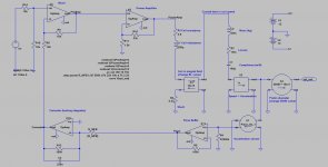
Here is a LTspiceIV modelization of the Philips MFB (Motional FeedBack) system.
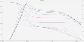
You can change the amount of MFB by changing the value of R_MFB. The smaller the value, the greater the amount of MFB applied.
1.
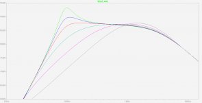
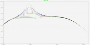
One can see that MFB does decrease the resonance frequency, but quite deceiving is to see that acoustic response gets even more peaking with MFB applied. The opamp used as corrector may be used for processing the feedback signal, in order to decrease the peaking. Then, we'll get a more sophisticated, more useable MFB system. This is to be carefully investigated.
2.
On the other hand, one can see that the effect of MFB is wideband, extending to 4 kHz. Actually, the practical limit is around 1 kHz because of the mechanical resonance of the piezo transducer. In this simulation, the piezo element simulation is a capacitor providing a voltage proportional to acceleration. It may be needed to refine the piezo element simulation, introducing a Laplace 2nd order lowpass at 1kHz with a decent Q factor like 3. We may then discover that the system gets unstable if there is a lot of MFB applied. This would enable us to better circumvent the practical limit of MFB to be applied, using a such piezo transducer.
3.
Actually, we are not interested in a wideband MFB scheme. We don't like the idea of wideband sound textures being governed by a piezo crystal. What we only need is a MFB system able to compensate the suspension linearities and magnetics nonlinearities occuring when the membrane excursion is considerable. In other words, we want the MFB to be confined inside the 20 Hz to 120 Hz range, the only domain where membrane excursion is considerable.
The 1-2-3 considerations above will help us designing a proper MFB scheme, providing a bass extension in the acoustic response, without peaking, confined to the 20 Hz to 120 Hz frequency range.
See attached files.
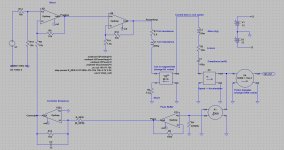
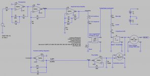
In this Philips MFB schematic, I have replaced the TL071 opamps (with their transistor-level spice simulation) and the Kuroda poweramp (with the transistor-level spice simulation) by a homemade OpAmp. This explains the unusual ground connexion associated to the OpAmp output. Take some time opening the schematic of this homemade OpAmp. The huge benefit of this backwards-move (we do no more a transistor-level simulation) is that we now get an extra-fast simulation speed. It takes less than one second for an .AC parametric sweep involving six different amounts of MFB being applied.
Cheers,
Steph
You can change the amount of MFB by changing the value of R_MFB. The smaller the value, the greater the amount of MFB applied.
1.
One can see that MFB does decrease the resonance frequency, but quite deceiving is to see that acoustic response gets even more peaking with MFB applied. The opamp used as corrector may be used for processing the feedback signal, in order to decrease the peaking. Then, we'll get a more sophisticated, more useable MFB system. This is to be carefully investigated.
2.
On the other hand, one can see that the effect of MFB is wideband, extending to 4 kHz. Actually, the practical limit is around 1 kHz because of the mechanical resonance of the piezo transducer. In this simulation, the piezo element simulation is a capacitor providing a voltage proportional to acceleration. It may be needed to refine the piezo element simulation, introducing a Laplace 2nd order lowpass at 1kHz with a decent Q factor like 3. We may then discover that the system gets unstable if there is a lot of MFB applied. This would enable us to better circumvent the practical limit of MFB to be applied, using a such piezo transducer.
3.
Actually, we are not interested in a wideband MFB scheme. We don't like the idea of wideband sound textures being governed by a piezo crystal. What we only need is a MFB system able to compensate the suspension linearities and magnetics nonlinearities occuring when the membrane excursion is considerable. In other words, we want the MFB to be confined inside the 20 Hz to 120 Hz range, the only domain where membrane excursion is considerable.
The 1-2-3 considerations above will help us designing a proper MFB scheme, providing a bass extension in the acoustic response, without peaking, confined to the 20 Hz to 120 Hz frequency range.
See attached files.
In this Philips MFB schematic, I have replaced the TL071 opamps (with their transistor-level spice simulation) and the Kuroda poweramp (with the transistor-level spice simulation) by a homemade OpAmp. This explains the unusual ground connexion associated to the OpAmp output. Take some time opening the schematic of this homemade OpAmp. The huge benefit of this backwards-move (we do no more a transistor-level simulation) is that we now get an extra-fast simulation speed. It takes less than one second for an .AC parametric sweep involving six different amounts of MFB being applied.
Cheers,
Steph
Attachments
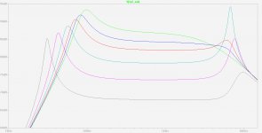
here are the result when introducing a mechanical resonance in the piezo sensor, along with a lowpass function representing the flexibility of the glue used to attach the piezo sensor. As expected, the system gets unstable when applying strong MFB. Now we can quantify the physical limit of MFB, in function of the internal resonance of the piezo sensor, and in function of the method used for attaching the acceleration sensor to the voice coil, dust cap or membrane.
We need to remember that Philips used flexible rubber instead of hard glue, as explicit lowpass filter, certainly an attempt to avoid stimulating the piezo sensor with frequencies approaching the internal resonance of the piezo sensor. The size of the Philips piezo sensor was quite small, so one can expect the internal resonance of it to be in the order of 15 kHz. In Philips MFB, the lowpass frequency and the Q factor of the acceleration measurement subsystem was thus under the control of rubber, plus under the control of the piezo element. There were thus two additional elements in series (piezo + rubber) defining the acoustic signature of the loudspeaker, in the frequencies that were under control of MFB.
This looks quite similar to the old piezo pickup technology of the early sixties, before the massive adoption of the moving coil pickup in the seventies. I have the impression that Philips did some recycling of their piezo pickup technology, for making up their MFB loudspeakers.
If we now use a 20 mm piezo disc like used in some miniature buzzers, fixed using hard glue, we should expect 2 kHz to 5 kHz as internal resonance frequency. With such arrangement, if the glue is infinitely hard, we only add one element (the piezo element), defining the sonic signature in the frequencies under control of MFB.
It is essential to know how the piezo sensor is generating the voltage.
In the Philips arrangement, I think it was more flexion than pressure. In the Philips arrangement, I think that the piezo was used as cantilever, with its own weight producing the inertia leading to bending, leading to a voltage. The rubber was there, for damping the two ends of the cantilever.
Other arrangements are possible like rigidly fixing the the whole surface of the piezo somewhere close to the end of the voice coil. You then don't allow the piezo to flex. You deliberatly lose a lot of sensitivity. You thus only rely on the pressure effect. To counterbalance the loss in sensitivity, you use a quite large piezo disc, much larger than the Philips one. You may use a 20 mm piezo disc. You may add an inertial mass on top of the piezo own mass, loading the surface of the piezo with a small adhesive mass, like pattex-enrobed sand. This layer provides an inertia mass (increase of sensitivity), and may provide an optimum damping for getting a 2nd order Bessel (Q=0.5) low pass.
However, at this stage, I have three questions :
1.
Could it be we need to isolate the 20 mm piezo disc from high frequencies ? Glueing the 20 mm piezo disc on a rubber support ? Any advice welcome.
2.
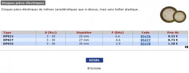
Can we buy piezo discs, much smaller than the 20 mm discs one can find in some piezo buzzers ? Where can we find this ?
3.
Is it allowed to cut a piezo disc for making it smaller ? What are the precautions for not destroying the device, if cutting it for making it smaller ? Any advice welcome.
Regards,
Steph
We need to remember that Philips used flexible rubber instead of hard glue, as explicit lowpass filter, certainly an attempt to avoid stimulating the piezo sensor with frequencies approaching the internal resonance of the piezo sensor. The size of the Philips piezo sensor was quite small, so one can expect the internal resonance of it to be in the order of 15 kHz. In Philips MFB, the lowpass frequency and the Q factor of the acceleration measurement subsystem was thus under the control of rubber, plus under the control of the piezo element. There were thus two additional elements in series (piezo + rubber) defining the acoustic signature of the loudspeaker, in the frequencies that were under control of MFB.
This looks quite similar to the old piezo pickup technology of the early sixties, before the massive adoption of the moving coil pickup in the seventies. I have the impression that Philips did some recycling of their piezo pickup technology, for making up their MFB loudspeakers.
If we now use a 20 mm piezo disc like used in some miniature buzzers, fixed using hard glue, we should expect 2 kHz to 5 kHz as internal resonance frequency. With such arrangement, if the glue is infinitely hard, we only add one element (the piezo element), defining the sonic signature in the frequencies under control of MFB.
It is essential to know how the piezo sensor is generating the voltage.
In the Philips arrangement, I think it was more flexion than pressure. In the Philips arrangement, I think that the piezo was used as cantilever, with its own weight producing the inertia leading to bending, leading to a voltage. The rubber was there, for damping the two ends of the cantilever.
Other arrangements are possible like rigidly fixing the the whole surface of the piezo somewhere close to the end of the voice coil. You then don't allow the piezo to flex. You deliberatly lose a lot of sensitivity. You thus only rely on the pressure effect. To counterbalance the loss in sensitivity, you use a quite large piezo disc, much larger than the Philips one. You may use a 20 mm piezo disc. You may add an inertial mass on top of the piezo own mass, loading the surface of the piezo with a small adhesive mass, like pattex-enrobed sand. This layer provides an inertia mass (increase of sensitivity), and may provide an optimum damping for getting a 2nd order Bessel (Q=0.5) low pass.
However, at this stage, I have three questions :
1.
Could it be we need to isolate the 20 mm piezo disc from high frequencies ? Glueing the 20 mm piezo disc on a rubber support ? Any advice welcome.
2.
Can we buy piezo discs, much smaller than the 20 mm discs one can find in some piezo buzzers ? Where can we find this ?
3.
Is it allowed to cut a piezo disc for making it smaller ? What are the precautions for not destroying the device, if cutting it for making it smaller ? Any advice welcome.
Regards,
Steph
Attachments

Last edited:
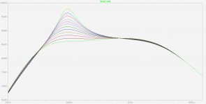
Here are the results when using a leaking integrator as feedback controller. There is no bass peaking anymore, the MFB effects gets now confined to the deep bass range, and we get an easy to pre-equalize acoustic output, if carefully chosing the amount of MFB. Could we ask more ?
Attachments
As expected, using some basic equalization, we get something useable. The equalization has been made within the closed loop with 1) a power amplifier now providing a strong bass boost (see the new feedback arrangement) and 2) the feedback controller now taking into account this bass boost (see the new values for R and C).
There is no bass peaking anymore, the MFB effects gets now confined to the deep bass range, and the acoustic response is essentially flat starting from 35 Hz, where the acoustic output is at -3 dB.
We shall now determine if this simple circuit arrangement enables any arbitrary bass extension. It could be that if one wants to go as deep as 18 Hz at -3 dB, that a more elaborate circuit is needed.
Steph
Attachments
-
 Philips MFB with resonant piezo and leaking integrator controller and equalized amp.jpg150.1 KB · Views: 275
 -
 Philips MFB with resonant piezo and leaking integrator controller and equalized amp (Bode plot).jpg105.1 KB · Views: 255
 -
Philips MFB with resonant piezo and leaking integrator controller and equalized amp.zip184.4 KB · Views: 164
Last edited:
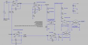
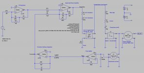
And now, the cherry on the pie, the MFB arrangement that provides an arbitrary bass extension.
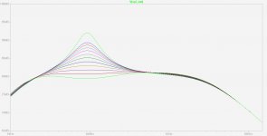
I will briefly describe the strategy that got applied. The big idea is that if we want a bigger bass extension than before, we'll need to apply more MFB. Then, if we change nothing else in the circuit, we get a less linear acoustic response. With such increased MFB, being now unable to get a horizontal flat 18 Hz to 100 Hz acoustic response, a proper solution is to target a deep bass response curve presenting a 1st order positive slope. Such ascending curve is easy to pre-equalize. This is thus the strategy.
We've thus trimmed the poweramp feedback network and the leaking integrator feedback network, for a 1st order positive slope acoustic response in the deep bass range. In the context of more MFB applied.
As you can see, the pre-equalizer is straightforward. It complements the 1st order ascending response curve between 30 Hz and 80 Hz. The pre-equalizer doesn't need to be based on an opamp. It can be passive if it is driven by a low impedance source. Remember however it is never the case when just after a volume pot.
If one has full control regarding the power amplifier, a good idea is to rewire it as an inverting amplifier. This saves one opamp in the circuitry.
I feel quite satisfied with such arrangement. Nothing seems critical. Everything can be adjusted at will.
It is quite impressive to realize that such uncomplicated circuitry has the capability to 1) linearize the bass and deep bass acoustic response 2) provide an arbitrary deep bass extension and c) decrease distorsion in the deep bass range.
One may ask why such MFB system is not universally used. There are three good reasons for that : 1) the amplifier must be matched to the loudspeaker and enclosure, 2) the enclosure must be a closed box, 3) bass-reflex and some other enclosure systems demand less cone excursion in the deep bass range than the closed box - they are thus less prone to distorsion in the deep bass range.
Are there examples of MFB applied to bass-reflex and other enclosure systems ? The cone acceleration doesn't represent anymore the acoustic response. One must take the acoustic emission of the vent in account, with phase and amplitude. Plus stability issues, maybe ?
Cheers,
Steph
Attachments
-
 Philips MFB with arbitrary bass extension.jpg151.6 KB · Views: 441
 -
 Philips MFB with arbitrary bass extension (Bode plot).jpg98.8 KB · Views: 294
 -
 Philips MFB with arbitrary bass extension with inverting poweramp.jpg147.8 KB · Views: 260
 -
 Philips MFB with arbitrary bass extension with inverting poweramp (Bode plot).jpg98.1 KB · Views: 249
 -
Philips MFB with arbitrary bass extension.zip357.2 KB · Views: 205
Thanks for your fascinating work and for posting it.
I'm wanting to understand the schematic more but dont know what X1,2,3,4 are in Ltspice. I have tried to load the model but get the following errors,
on opening "Philips MFB with arbitrary bass extension.asc"-
---------------------------
LTspice IV
---------------------------
Couldn't find symbol(s):
BL
Differentiator
Piston
Piezo_5k_1
---------------------------
OK
---------------------------
and on starting simulation-
-------------------------
SPICE Error
---------------------------
Unknown subcircuit called in:
xx8 nc_01 nc_02 nc_03 opamp aol=100k gbw=10meg
---------------------------
OK
---------------------------
I'm very interested in the loop response, esp loop gain, and phase response (of the loop).
On your schematic directory, you need to add the subcircuits given in post #5 above. If there is still a "SPICE Error", you need to tell LTspice to use "my custom library" given in post #5 above.Couldn't find symbol(s) :BL, Differentiator, Piston, Piezo_5k_1 ; on starting simulation : "SPICE Error" ; "Unknown subcircuit called in: xx8 nc_01 nc_02 nc_03 opamp aol=100k gbw=10meg"
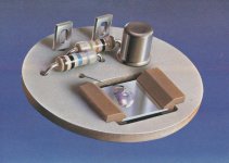
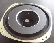
First generation Philips "PXE sensor" used into all cone-shaped MFB woofers (AD8065/MF4, AD7066/MF4, AD8066/MF4, AD10066/MF4) like used in the RH432, RH541, RH544, RH545, RH567, RH585, RH586, RH587 speaker systems. See attached pictures.
Attachments
Last edited:
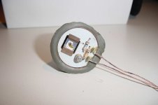
Philips sensor used in all flat-membrane MFB woofers like the F9638 speaker system. See attached pictures. Is it a round-shaped PCB or is it a Piezo disc ? Are the required JFET and two resistors glued at the back ?
Attachments
Last edited:
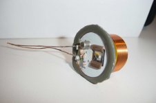
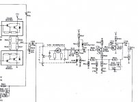
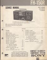
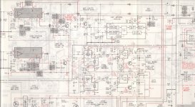
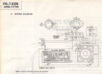
Sony MFB system. See attached pictures. What is the sensor ? Where is the sensor ? Look the "MFB+" and "MFB-" terminals on the power amp. Look the schematic around them.
Attachments
Last edited:
On your schematic directory, you need to add the subcircuits given in post #5 above. If there is still a "SPICE Error", you need to tell LTspice to use "my custom library" given in post #5 above.
Almost there, now all I get is-
---------------------------
LTspice IV
---------------------------
Couldn't find symbol(s):
Piezo_5k_1
---------------------------
OK
---------------------------
The schematic loads and simulates but cant display the piezo.
Looking at the conditionning circuitry, it has to be a low impedance type, probably an auxiliary coil.Sony MFB system. See attached pictures. What is the sensor ? Where is the sensor ? Look the "MFB+" and "MFB-" terminals on the power amp. Look the schematic around them.
That's also confirmed by the presence of the integrator.
Almost there, now all I get is-
---------------------------
LTspice IV
---------------------------
Couldn't find symbol(s):
Piezo_5k_1
---------------------------
OK
---------------------------
The schematic loads and simulates but cant display the piezo.
Found it on post #6
I've looked at the loop gain of the circut with the greatest gain set (RMFB=39K) and it peaks at only 4 at about 90Hz, dropping off rapidly either side. With 150K the loop gain peaks at 1!.And now, the cherry on the pie, the MFB arrangement that provides an arbitrary bass extension.
....
From a Control Systems point of view a loop gain of 4 is minute. For comparison opamps used as a buffer in audio gear boast great specs by having a loop gain of about 100 000 at 90Hz.
The limited loop gain would reduce some harmonics (but its only really there over a small frequency band) but would also cause a dip in the fundamental. Perhaps this is made up by some boost in a previous filter.
I would really like to get my hands on a good transducer and see whats possible.
Going a bit O.T., Steph, could you please elaborate how you go from T.S. parameters to the speaker model you have in LtSpice? I would like to use this method for analysing possibilities.
....
Going a bit O.T., Steph, could you please elaborate how you go from T.S. parameters to the speaker model you have in LtSpice? I would like to use this method for analysing possibilities.
Is it possible to have a cone excursion output too?
Following this Thiele/Small wiki : Thiele/Small - Wikipedia, the free encyclopedia, you get the T/S parameters in function of the mechanical parameters. If you want the mechanical parameters in function of the T/S parameters, it becomes a classic inversion problem. Try the Mathcad symbolic processor. Or do it by hand.Could you please elaborate how you go from T.S. parameters to the speaker model you have in LTspice? I would like to use this method for analysing possibilities.
- Status
- This old topic is closed. If you want to reopen this topic, contact a moderator using the "Report Post" button.
- Home
- Loudspeakers
- Multi-Way
- Philips Motional Feedback (MFB)