hello,
however very interesting to read, this post is slightly drifting out of subject. Aren't we supposed to talk about Servo-Sound here ? This is a system NOT involving a dedicated sensor. This is a system aiming at recovering the motional voltage (back EMF if you want to call it so), sensing the currents and sensing the voltages in different locations of the circuit.
Don't you think that the unity damping concept can deliver something usefull ? Not directly, but indirectly, for being able to extract (or synthesize should I write) the back EMF with great precision, even in the presence of factory dispersion, thermal drift and aging effects ? See post #6 and post #12.
And, can somebody help me determine what's inside the Servo-Sound "black box" ?
Cheers,
Steph
Last edited:
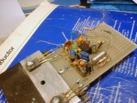
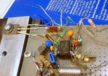
Unfortunately, I don't understand. Is a less cryptic description available ?The two pictures could give you some clues about the insides of Servo-Sound "black box": it is a thermal image shunt.
Attachments
I've just made a dedicated thread about the Philips MFB system.
http://www.diyaudio.com/forums/solid-state/166061-philips-motional-feedback-mfb.html#post2170963
http://www.diyaudio.com/forums/solid-state/166061-philips-motional-feedback-mfb.html#post2170963
The behavior of the shunt mimics that of the voice-coil: temperature coefficient, time constants, self-heating, etc.Unfortunately, I don't understand. Is a less cryptic description available ?
So basically it is a variable gain amp ?The behavior of the shunt mimics that of the voice-coil: temperature coefficient, time constants, self-heating, etc.
Once we know the math equations to be implemented, would a dsPIC33 be able to sample the current (and voltage maybe) at Fs = 1 kHz or 10 KHz depending on the complexity of the maths, and drive a precision volume control like a CS3310 ? The circuit would be more compact than the analog counterpart.
Or, do we absolutely need a continuously variable resistance for avoiding "clicks" when the circuit adjusts ? This would require a transconductance amp analog driven ? So bye-bye the digital approach ?
What are the maths to be computed, based on what signals ? With a 6 ohm voice coil at 25 deg centigrade, what is the max correction needed ?
What if the copper is not exactly the copper you are expecting ? Like aluminium ?
Is there any way to do the resistive measurement in closed loop, instead of guessing what it may be ? Like adding a digitally generated subsonic 1 Hz -10 Hz 10mV test pattern voltage on top of the audio signal, and analysing how it shows as current ? Using steep digital filtering and correlation for improving the signal/noise. The resulting signal, indeed, would be a 1mA 1 Hz - 10 Hz signal buried into a 100V audio signal.
Is the copper resistance variation the only difficulty preventing the Servo-Sound system to operate with a close to 100% virtual DC coil resistance suppression ? What suppression coefficient would you use ? 80% like in the early experiments back in 1957 ? Or 95% if you manage to measure and virtually negate the DC coil resistance with a 1% uncertainty ?
How can you know you are "exact" ? It is still open loop, regarding the DC coil resistance emulation.
We need to think about the closed-loop auto-focus strategy using the particular signature that emerges when the system is virtually driven using a unity damping factor. Let us start now, only dealing with the DC resistance. Let us neglect, for the moment, the reactive components.
Steph
Last edited:
Pardon me if I repeat myself, but copper temperature (.39% per degree C) is a big issue for modelers but not for audiophiles. I have no solid evidence to say so, but I doubt that playing music at home leads to hot voice coils, even warm voice coils - correct me if I am wrong.
Yes, you can't be PERFECT unless you bridge-out the DC resistance of the coil and that changes with temperature a wee bit in home applications. But certainly not worth fretting about.
Aluminum, copper, titanium.... carbon nanotubes.... what difference could it really make.
Go experiment. Devise clever, representative, and convincing test protocols that will allow you to consistently gauge your progress.
In a small way, yes, but that 's not the way I would describe it.So basically it is a variable gain amp ?
It is rather a compensated negative impedance amplifier.
It is certainly possible to sample the current using a conventional, stable shunt, create in software a thermal image of the voice coil, and fine-tune the amount of negative resistance accordingly.Once we know the math equations to be implemented, would a dsPIC33 be able to sample the current (and voltage maybe) at Fs = 1 kHz or 10 KHz depending on the complexity of the maths, and drive a precision volume control like a CS3310 ? The circuit would be more compact than the analog counterpart.
It wouldn't be more compact, quite the contrary: you still need the analog power amplifier configured for negative resistance, but you have to add the DSP engine, plus interfaces between the digital and analog circuits: an ADC to acquire the current, and some form of DAC to control the negative resistance.
In addition, a temperature sensor near the loudspeaker is still required, to take the ambient temperature into account.
IMO, this is a minor issue: you could use some form of interpolation or similar to smooth the steps.Or, do we absolutely need a continuously variable resistance for avoiding "clicks" when the circuit adjusts ? This would require a transconductance amp analog driven ? So bye-bye the digital approach ?
Ideally, for 6 ohm DC resistance, a correction of -6ohm is required... but it is not a realistic option.What are the maths to be computed, based on what signals ? With a 6 ohm voice coil at 25 deg centigrade, what is the max correction needed ?
It is like any compensation: it depends on the lengths you go to insure accuracy.What if the copper is not exactly the copper you are expecting ? Like aluminium ?
Doing that is possible, problem is, you will get an average on a number of seconds.Is there any way to do the resistive measurement in closed loop, instead of guessing what it may be ? Like adding a digitally generated subsonic 1 Hz -10 Hz 10mV test pattern voltage on top of the audio signal, and analysing how it shows as current ? Using steep digital filtering and correlation for improving the signal/noise. The resulting signal, indeed, would be a 1mA 1 Hz - 10 Hz signal buried into a 100V audio signal.
This is not sufficient if you want to achieve a good degree of correction: at high power levels, the resistance varies significantly and quickly with the music program.
Even individual half-cycles at low frequencies, tens of Hz, alter dynamically this resistance.
It is important to take these effects into account, not only because they affect the accuracy of the "static" correction, but also because they cause distortions:
If you have a thermally induced distortion of 1% at 40Hz on the uncorrected speaker, and you cancel 90% of the of the resistance using a linear negative resistance, the 10% left will still carry the same absolute level of non-linearity, pushing the distortion to 10%. This becomes unacceptable.
No, when you correct the speaker, it becomes more "perfect", with a (virtual) electrical/acoustical efficiency approaching 100%.Is the copper resistance variation the only difficulty preventing the Servo-Sound system to operate with a close to 100% virtual DC coil resistance suppression ? What suppression coefficient would you use ? 80% like in the early experiments back in 1957 ? Or 95% if you manage to measure and virtually negate the DC coil resistance with a 1% uncertainty ?
This increases the effective gain enormously, and it is not easily manageable.
This type of correction is only applicable to low frequencies, because phase shifts and mechanical difficulties make it unusable and unstable at frequencies over a few hundred hertz.
This means you have to filter higher frequencies away from the correction, but this leads to huge gain imbalances between the frequency bands, as higher frequencies do not benefit from the boost provided by the negative resistance.
90% is still manageable, but going beyond becomes very quickly impractical, as tiny variations in any of the parameters has a disproportionate impact on the result.
You can compute the component values to yield a certain value, or alternatively you can measure and adjust it.How can you know you are "exact" ? It is still open loop, regarding the DC coil resistance emulation.
Say you want -5.5 ohm correction for your 6 ohm speaker, you apply an input signal to get 1V with the amplifier unloaded; you connect a 11 ohm load, and you adjust the negative resistance to see 2V output.
You now have adjusted your amplifier for -5.5 ohm. This, of course, has to be done at low levels to avoid heating the shunt.
There is a simple experiment that will convince you to the contrary:Pardon me if I repeat myself, but copper temperature (.39% per degree C) is a big issue for modelers but not for audiophiles. I have no solid evidence to say so, but I doubt that playing music at home leads to hot voice coils, even warm voice coils - correct me if I am wrong.
Yes, you can't be PERFECT unless you bridge-out the DC resistance of the coil and that changes with temperature a wee bit in home applications. But certainly not worth fretting about.
You just have to put your speaker in a bridge arrangement.
Make the measurement at 50Hz f.e. You balance the bridge for a low power level, 0.1W.
Then, increase the power to 10W: you will see the balance go away.
Once it is settled, you can rebalance it, but you won't be able to remove the residue completely: harmonics will remain.
If you want to remove mechanical effects from the test, you can repeat it with the voice coil immobilized: you will still get non-linear effects, meaning thermal effects are to blame.
Attachments
Even to an amateur like me, I see weird fantasies taking hold in this discussion.
1. If we are talking of non-mic feedback based on motion of the cone, then we are only talking about piston-range frequencies below maybe 200Hz where the motion of the dust cap of the driver closely relates to the sound in the room. Calm down everybody, no need to rummage in your parts box for RF ceramic capacitors and worry about the final particle of EXACT balance. HF drivers are full of serious magic and, for the moment, I see little scope for MF there.
2. The kind of shift of bridge balance from hot coils (not that I agree they become hot) or any other kind of misbalance does not result in the kind of signal distortion we hear. At worst it is some kind of slight and slow change in amplification. It isn't distortion in any important sense and, once again, not worth fretting about.
3. Bridges are fantastically sensitive, ask Wheatstone. Just because you can put an ear-splitting 10 watts into a woofer for three minutes (before it self-destructs) and thus imbalance in a bridge (to a degree that is not easy to evaluate) doesn't mean much in practical life. How about some evidence from a thermometer... and that doesn't take continuous 10 watts, not even an organ pedal in Franck's music ever does that.
As I've been saying, you grab some MF feedback and run with it. How much, how much emulation is needed in the "black box," how to keep things stable, how to limit MF action to pioston-range, these are useful empirical questions.
I am certainly not the one promoting weird fantasies here.Even to an amateur like me, I see weird fantasies taking hold in this discussion.
My approach and my results have a quantitative foundation, based on measurements, calculations, and application of elementary physics.
1. If we are talking of non-mic feedback based on motion of the cone, then we are only talking about piston-range frequencies below maybe 200Hz where the motion of the dust cap of the driver closely relates to the sound in the room. Calm down everybody, no need to rummage in your parts box for RF ceramic capacitors and worry about the final particle of EXACT balance. HF drivers are full of serious magic and, for the moment, I see little scope for MF there.
Who said otherwise? I didn't:
This type of correction is only applicable to low frequencies, because phase shifts and mechanical difficulties make it unusable and unstable at frequencies over a few hundred hertz.
Let's compute the temperature rise for a voice coil containing 2.6 gram of copper, connected to a 50W amplifier.2. The kind of shift of bridge balance from hot coils (not that I agree they become hot) or any other kind of misbalance does not result in the kind of signal distortion we hear. At worst it is some kind of slight and slow change in amplification. It isn't distortion in any important sense and, once again, not worth fretting about.
1 gram of copper has a specific heat of 2.6°K/J.
A 50W amplifier can deliver 100W instantaneous power. This will be the case during the attack of some instruments, if the amplifier is operated just below the clipping limit. At 100W, the coil's temperature will rise at a rate (100*2.6)/2.6 ~=100°C/s for adiabatic conditions.
For short bursts, the adiabatic approximation is valid. During 10ms (half a 50Hz cycle), the coil will gain 1°C, and its resistance will rise ~0.4%.
Under normal conditions, this non-linearity is small, and will probably be masked by other distortions. But if the speaker is included in a 90% effective resistance cancellation driver, the non-linearity will be magnified to 4%.
Voice coils can heat and do heat (sometimes, they even burn): that's why high power drivers have theirs wound on a polyimide or kapton coil former.3. Bridges are fantastically sensitive, ask Wheatstone. Just because you can put an ear-splitting 10 watts into a woofer for three minutes (before it self-destructs) and thus imbalance in a bridge (to a degree that is not easy to evaluate) doesn't mean much in practical life. How about some evidence from a thermometer... and that doesn't take continuous 10 watts, not even an organ pedal in Franck's music ever does that.
A 100°C rise has nothing extraordinary.
hello,
I know bentoronto may disagree with this : it may be interesting to document and model using LTspiceIV, in a step-by-step & pedagogic approach :
0 - a conventional loudspeaker (closed box arrangement) fed by a conventional amplifier
1 - the experiments dating back from 1957 with a 80% cancellation of the cold copper resistance
2 - one of those GEGO combined pick-up + amp + speakers "stereo electrophone" in french, dating back from the late sixties (I have the full schematics)
3 - a first generation Korn-Macway (aka Servo-Sound) implementation (I have the schematics but don't know what's inside the black box)
4 - a first generation Yamaha AST (Active Servo Technology) amplifier along with the "by default" personality module (I have the schematics)
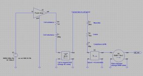
For modelling the speaker driver in the closed enclosure, I suggest we use the intuitive good old way, so everybody will be able to understand what's going on. No need to refer to the Thiel-Small theory. LTspiceIV will in fact illustrate the Tiele-Small theory. With the advantage of being able to focus on the back EMF (motional voltage) extraction.
1 - The coil mechanical force is proportional to the instantaneous current in the coil. This relation gets represented in our LTspiceIV model using a current controlled voltage source. The resulting voltage is thus the instantaneous force.
2 - This mechanical force tends to create a mechanical displacement of the coil. If the system has a mass, the force creates an acceleration. If the system has a compliance, the force creates a displacement. If the system has imperfections, the force dissipates. A real loudspeaker driver embeds those three components.
3 - In our LTspiceIV closed box model, if we chose the coil speed as operational variable, the coil speed is equivalent to the current (not a physical current, but a current flowing somehere in the model) flowing through the mass + compliance + dissipative element put in series. You need to think about this deeply : why do we arrange those three components (mass, compliance, dissipation) in series, submitting them to a same "current" which is the voice coil speed, with an global voltage on them that is the voice coil force. You may say that point 3 is like entering in religion, but if you think twice you will see that there is a physical reason for designing the whole thing this way. This kind of reflexion will help you understand, later on, why and were we need to add components like in a 4th order bass reflex box, or like in a 4th order dualchamber box.
4 - Very fortunately in such conception, mass is equivalent to inductance because high frequency voltage = high frequency force, so it means less current through it = less mechanical displacement. Dissipation is equivalent to resistance. Compliance is equivalent to capacitance because with coil speed being the current through it, by integrating the coil speed over time you get the excursion, and the excursion is of course proportional to compliance.
5 - There is a back EMF generated proportional to the speed of the coil. So now you understand why above, we selected the coil speed as operational variable in our LTspiceIV model. This relation gets represented in our LTspiceIV model as a current controlled voltage source.
6 - This resulting back EMF voltage source is wired in series with the source voltage (amplifier output), with the correct sign. There is your "motional voltage", actually.
7 - After all this being said, one should remember that the acoustic pressure is not proportional to the coil speed, but proportional to the coil acceleration. So if one wants to draw SPL diagrams, one needs to differentiate over time (speed/time) the "current" flowing in our LTspiceIV model. We will thus need to create a "p" or "s" LTspiceIV subcircuit.
8 - And now, because you know both the acceleration of your membrane, and the size of the radiating surface of your membrane (piston surface), you know the instantaneous acoustic pressure. Without needing to read Thiel-Small litterature, but using the same language and variables as Thiele-Small.
Actually, this is Thiele-Small explained in plain english, with LTspiceIV doing the maths.
I let you think about this, so you can make up your mind.
Next week I will post the correspondent LTspiceIV schematic for a loudspeaker driver in free air.
Immediately after, we will see how compliance gets reduced when mounting this loudspeaker driver in a closed box. This is an application of the physical law of gases saying that Pressure x Volume = constant. As a result, we'll get the LTspiceIV model of a closed box loudspeaker.
Such model can handle everything, including non-linearities if we define non-linear components inside the BL factor (magnetic saturation + coil quitting the constant magnetic field area), inside the compliance (limited excursion), and inside the coil resistance (temperature dependency).
Cheers,
Steph
I know bentoronto may disagree with this : it may be interesting to document and model using LTspiceIV, in a step-by-step & pedagogic approach :
0 - a conventional loudspeaker (closed box arrangement) fed by a conventional amplifier
1 - the experiments dating back from 1957 with a 80% cancellation of the cold copper resistance
2 - one of those GEGO combined pick-up + amp + speakers "stereo electrophone" in french, dating back from the late sixties (I have the full schematics)
3 - a first generation Korn-Macway (aka Servo-Sound) implementation (I have the schematics but don't know what's inside the black box)
4 - a first generation Yamaha AST (Active Servo Technology) amplifier along with the "by default" personality module (I have the schematics)
For modelling the speaker driver in the closed enclosure, I suggest we use the intuitive good old way, so everybody will be able to understand what's going on. No need to refer to the Thiel-Small theory. LTspiceIV will in fact illustrate the Tiele-Small theory. With the advantage of being able to focus on the back EMF (motional voltage) extraction.
1 - The coil mechanical force is proportional to the instantaneous current in the coil. This relation gets represented in our LTspiceIV model using a current controlled voltage source. The resulting voltage is thus the instantaneous force.
2 - This mechanical force tends to create a mechanical displacement of the coil. If the system has a mass, the force creates an acceleration. If the system has a compliance, the force creates a displacement. If the system has imperfections, the force dissipates. A real loudspeaker driver embeds those three components.
3 - In our LTspiceIV closed box model, if we chose the coil speed as operational variable, the coil speed is equivalent to the current (not a physical current, but a current flowing somehere in the model) flowing through the mass + compliance + dissipative element put in series. You need to think about this deeply : why do we arrange those three components (mass, compliance, dissipation) in series, submitting them to a same "current" which is the voice coil speed, with an global voltage on them that is the voice coil force. You may say that point 3 is like entering in religion, but if you think twice you will see that there is a physical reason for designing the whole thing this way. This kind of reflexion will help you understand, later on, why and were we need to add components like in a 4th order bass reflex box, or like in a 4th order dualchamber box.
4 - Very fortunately in such conception, mass is equivalent to inductance because high frequency voltage = high frequency force, so it means less current through it = less mechanical displacement. Dissipation is equivalent to resistance. Compliance is equivalent to capacitance because with coil speed being the current through it, by integrating the coil speed over time you get the excursion, and the excursion is of course proportional to compliance.
5 - There is a back EMF generated proportional to the speed of the coil. So now you understand why above, we selected the coil speed as operational variable in our LTspiceIV model. This relation gets represented in our LTspiceIV model as a current controlled voltage source.
6 - This resulting back EMF voltage source is wired in series with the source voltage (amplifier output), with the correct sign. There is your "motional voltage", actually.
7 - After all this being said, one should remember that the acoustic pressure is not proportional to the coil speed, but proportional to the coil acceleration. So if one wants to draw SPL diagrams, one needs to differentiate over time (speed/time) the "current" flowing in our LTspiceIV model. We will thus need to create a "p" or "s" LTspiceIV subcircuit.
8 - And now, because you know both the acceleration of your membrane, and the size of the radiating surface of your membrane (piston surface), you know the instantaneous acoustic pressure. Without needing to read Thiel-Small litterature, but using the same language and variables as Thiele-Small.
Actually, this is Thiele-Small explained in plain english, with LTspiceIV doing the maths.
I let you think about this, so you can make up your mind.
Next week I will post the correspondent LTspiceIV schematic for a loudspeaker driver in free air.
Immediately after, we will see how compliance gets reduced when mounting this loudspeaker driver in a closed box. This is an application of the physical law of gases saying that Pressure x Volume = constant. As a result, we'll get the LTspiceIV model of a closed box loudspeaker.
Such model can handle everything, including non-linearities if we define non-linear components inside the BL factor (magnetic saturation + coil quitting the constant magnetic field area), inside the compliance (limited excursion), and inside the coil resistance (temperature dependency).
Cheers,
Steph
Last edited:
I've been reading a lot of the literature past few days. For every possible permutation of positive, zero, and negative output impedance and in all degrees, there is some learned person who advocates it is THE mathematically necessary solution.The only thing I have found across all the papers I've looked at is that nobody seems to care about copper temperature coefficient. Most don't care about coil inductive values.
At some point, infinite introspection, as in this thread, will become self-parodying, like the bird that chases its tail until....
Time to get out the soldering iron and experiment. The performance is MF is too challenging to parse in a dark room with your computer instead of a little bit of testing.
hello,
however very interesting to read, this post is slightly drifting out of subject. Aren't we supposed to talk about Servo-Sound here ? This is a system NOT involving a dedicated sensor. This is a system aiming at recovering the motional voltage (back EMF if you want to call it so), sensing the currents and sensing the voltages in different locations of the circuit.
Don't you think that the unity damping concept can deliver something usefull ? Not directly, but indirectly, for being able to extract (or synthesize should I write) the back EMF with great precision, even in the presence of factory dispersion, thermal drift and aging effects ? See post #6 and post #12.
And, can somebody help me determine what's inside the Servo-Sound "black box" ?
Cheers,
Steph
As I recall Practical Electronics had an active speaker box design based on this idea a number of years ago.
Motional feed back amplifier
There rational was that above the box resonant frequency the mass of the cone dominates the motional impedance and thus the current in the voice coil is a representation of the force on the cone. Because force equals mass x acceleration the force and hence the current in the voice coil is analogous to the cone acceleration.
They sense the current through the voice coil and feed it back as a voltage developed across a sensing resistor. But this is no different than negative current feedback used to increase the amplifier output impedance.
The main advantage of this scheme is driving a speaker with constant current instead of constant voltage and avoiding non linearities with voice coil inductance which could be fairly bad for a small speaker.
The main disadvantage would be raising the Q of the system response at resonance and thus causing a large peak in the response at the box resonant frequency. As well this type of feedback does nothing to flatten the response below the resonant frequency.
regards
Trevor
Last edited:
I have just come full circle having followed Forr's link from the "forgotten techniques" thread on the Audax forum.
I surfed the Audax forum and found Bruno & Jean-Claude (aka JCB) who have created a Sub-woofer based on the JBL W15GTI. JCB to the British is an “earth mover” (mechanical excavator) and that sub must be the same!
The sub uses some ideas on negative impedance output amplifiers which I used on my Consort design. Ian Hegglun pointed out in an article in Wireless World that it was a form of motional feedback. Jean Claude has spent 40 years developing the idea having been impressed by the Servo-sounds
My blog:
Consort3′s Blog
Trevor's Practical Electronic circuit shows a very interesting feature: if the amp output phase is right, ANYBODY can experiment with MF with ANY amp by just adding a resistor to their speaker "reference" output terminal and maybe fuss a tiny bit inside with the pre-existing neg. feedback. Roughly what I've been pointing out about the Kenwood Basic M1 "Sigma Drive" amps.
This concept has been showing uyp in commercial hifi gear forever - or at least as far back an obscure but truly beautiful purple Fisher mono tube amp that had variable MF in late '50s, I'd guess.
But to help Trevor a bit, I find it easiest to think in terms of speaker impedance. If the impedance of the speaker rises due to back-EMF (for example, at resonance or for other reasons correlated with cone motion) it "grabs" less power from the amp when the driver impedance is being mirrored by internal impedance of the amp.
That controls resonance and lets you feed the speaker whatever power is needed to keep it on an even keel despite the speaker system's wishes... which is exactly what you want.
The main disadvantage would be raising the Q of the system response at resonance and thus causing a large peak in the response at the box resonant frequency.
Maybe this is an amplifier for dipoles with low Qts drivers?
Trevor's Practical Electronic circuit shows a very interesting feature: if the amp output phase is right, ANYBODY can experiment with MF with ANY amp by just adding a resistor to their speaker "reference" output terminal and maybe fuss a tiny bit inside with the pre-existing neg. feedback. Roughly what I've been pointing out about the Kenwood Basic M1 "Sigma Drive" amps.
This concept has been showing uyp in commercial hifi gear forever - or at least as far back an obscure but truly beautiful purple Fisher mono tube amp that had variable MF in late '50s, I'd guess.
But to help Trevor a bit, I find it easiest to think in terms of speaker impedance. If the impedance of the speaker rises due to back-EMF (for example, at resonance or for other reasons correlated with cone motion) it "grabs" less power from the amp when the driver impedance is being mirrored by internal impedance of the amp.
That controls resonance and lets you feed the speaker whatever power is needed to keep it on an even keel despite the speaker system's wishes... which is exactly what you want.
Yes you can do all of this to flatten frequency response but it doesn't compensate for BL and inductance non linearities. Only a true mfb system with a sensor to detect cone acceleration or velocity can reduce distortion in a loudspeaker.
regards
Trev
Sony sub with 12" driver, 180 watt amp and motional feedback
at 130 $...
Sony SA-W3000 12" 180W Amplified Subwoofer (SA W3000) at Vanns.com
at 130 $...
Sony SA-W3000 12" 180W Amplified Subwoofer (SA W3000) at Vanns.com
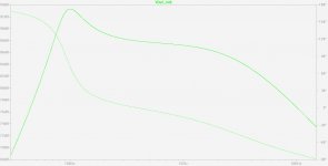
Attached you will find the continuation of post #30 about modelling a loudspeaker in fee air, using LTspiceIV.
See the attached pictures, and enjoy !
Steph
See the attached pictures, and enjoy !
Steph
Attachments
Last edited:
- Status
- This old topic is closed. If you want to reopen this topic, contact a moderator using the "Report Post" button.
- Home
- Amplifiers
- Solid State
- Servo-Sound made in Belgium