hello,
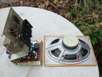
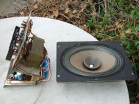
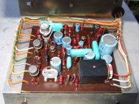
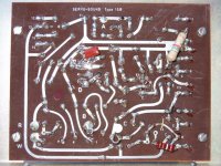
I just found two Servo-Sound loudspeakers. I just dismantled them. See the pictures. Can somebody provide the schematics ? It reads "type 15B" on the PCB.
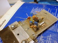
This is a interesting device because the little black box on the PCB is sampling the voltage potential that's developping on a small resistor inserted in series with the loudspeaker, and from what I can see, this black box generates the feedback to the amplifier, in the bass range.
Obviously, the aim of such feedback is to extend the bass response, ironing out the typical closed box woofer resonance. Kind of motional voltage synthesis, so the whole amp gets motional-voltage feedbacked, instead of voltage feedbacked. In the bass range. That was the big sales argument claimed by Servo-Sound.
From my experience, if you try a bass extension like this, using equalization in a closed box, due to the limited power and limited excursion of the woofer it is necessary to reduce the bass extension at high volumes. That is maybe the role of the bulb, maybe used as variable high-pass filter at the input, with the cold wire resistance decreasing with the AC audio current it sees. I can't see any LDR, so I'm quite confident that this bulb sees the AC audio signal, and is the variable element needed. But, on the other hand, one may expect a lot of distorsion if the thermal reaction time is faster than the audio signal ...
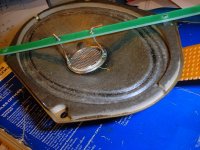
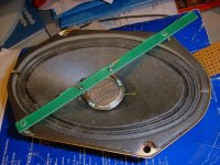
Note the unusual design of the loudspeaker chassis. It is truly rectangular, covering the whole surface of the baffle. First first time I see something like this. Kind of integration of the driver and the front of the baffle. The idea sounds right, but do you realize that if you want to redesign or upgrade the loudspeaker you need again to order one with a custom-made chassis ? What a nightmare, indeed ...
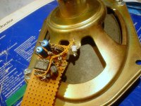
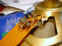
Cabling looks high quality like military or aeronautics. But look how far the power transistors are from the PCB ! And see how small and how far the rectifying bridge is, far from the filtering cap, and far from the transformer. That's completely mad !
Doesn't surprise me too much they stopped trading.
Their concept of an active loudspeaker integrating some smart equalization and variable high-pass for meeting the safe operating area of the driver, is still valid.
Therefore I'm sad they stopped trading.
So, if somebody could provide more info like a schematic of this Servo-Sound 15B version, that will be very welcome.
Steph
I just found two Servo-Sound loudspeakers. I just dismantled them. See the pictures. Can somebody provide the schematics ? It reads "type 15B" on the PCB.
This is a interesting device because the little black box on the PCB is sampling the voltage potential that's developping on a small resistor inserted in series with the loudspeaker, and from what I can see, this black box generates the feedback to the amplifier, in the bass range.
Obviously, the aim of such feedback is to extend the bass response, ironing out the typical closed box woofer resonance. Kind of motional voltage synthesis, so the whole amp gets motional-voltage feedbacked, instead of voltage feedbacked. In the bass range. That was the big sales argument claimed by Servo-Sound.
From my experience, if you try a bass extension like this, using equalization in a closed box, due to the limited power and limited excursion of the woofer it is necessary to reduce the bass extension at high volumes. That is maybe the role of the bulb, maybe used as variable high-pass filter at the input, with the cold wire resistance decreasing with the AC audio current it sees. I can't see any LDR, so I'm quite confident that this bulb sees the AC audio signal, and is the variable element needed. But, on the other hand, one may expect a lot of distorsion if the thermal reaction time is faster than the audio signal ...
Note the unusual design of the loudspeaker chassis. It is truly rectangular, covering the whole surface of the baffle. First first time I see something like this. Kind of integration of the driver and the front of the baffle. The idea sounds right, but do you realize that if you want to redesign or upgrade the loudspeaker you need again to order one with a custom-made chassis ? What a nightmare, indeed ...
Cabling looks high quality like military or aeronautics. But look how far the power transistors are from the PCB ! And see how small and how far the rectifying bridge is, far from the filtering cap, and far from the transformer. That's completely mad !
Doesn't surprise me too much they stopped trading.
Their concept of an active loudspeaker integrating some smart equalization and variable high-pass for meeting the safe operating area of the driver, is still valid.
Therefore I'm sad they stopped trading.
So, if somebody could provide more info like a schematic of this Servo-Sound 15B version, that will be very welcome.
Steph
Attachments
Last edited:
hello,
in past century (that's not so long ago) I did some simulations of motional feedback loudspeakers using spice, comparing the Philips MFB (using an acceleration sensor), the Servo-Sound (relying on an electronic synthesis of the motional voltage), and the Yamaha AST (Active Servo Technology which at the origin is an embryonic Servo-Sound arrangement with a limited correction range).
The problem with the Servo-Sound method and with the Yamaha AST method was to have the motional bridge accurately reflecting the electric equivalent schematic embedding the Thiele-Small parameters in the said-to-be-so closed box.
Later on Yamaha came with other sorts of AST designs, like the AST that are now used in their active subwoofers that are no closed box anymore. I should get a service manual and see what's inside. Can anybody point a link ?
Anyway, due to the fact that the motional impedance bridge was always inaccurate (factory tolerances and temperature effects in the loudspeaker), the feedback was never accurate. Coil resistance variation with temperature was one of the issue, disabling the possibility to drive the coil with a negative resistance exactly equal to to the coil resistance. This is actually needed for getting a purely motional-voltage driven system. In such an arrangement, the loudspeaker becomes a big and powerful microphone, telling you in realtime if the acoustic output is different from what it should be. And this mike becomes thus the feedback source of the whole amp. This is indeed the theoretical aim of a 100% pure Servo-Sound arrangement. Nice, isn't ?
I then wanted to measure the resistance of the coil, realtime, for driving a variable resistor in the motional bridge arrangement. Never came to something decent. Always a kind of rocket-scientist solution, unpractical.
I also wanted to be able to measure the accuracy of this simulated motional bridge, like the autofocus block of your your digicam is working. Back in the nineties, this was perceived like madness. Like autofocus was perceived like madness before World War II. What is the signal indicating that your synthesized electric schematic circuit is on focus ? You say it is the resulting signal itself ? Come on, are you mad ? Well, quite surprising, there might be something in the recovered audio signal itself (the motional voltage), indicating that the synthesized electric schematic is on focus. Kind of signature. Because there are magnetics involved. Nice field of research, isn't ?
I still believe that is the clear future of Rice-Kellogg moving coil loudspeaker patented in 1924, in the long range. Synthesizing the equivalent electronic schematic, isolating the motional impedance, measuring the instantaneous voltage on it, using this voltage as global feedback signal, plus a management block ensuring that the synthesized motional impedance is kept on focus whatever the actual conditions, factory dispersions and temperature effects.
You can't do it using bare DSP. Because of the processing delays. You only can do it with the DSP modifying the values of the analog components materializing your synthesized motional bridge.
Which means that you need electronic equivalents of a continuously variable resistor, capacitor and self, with the added difficulty that some cannot be single-ended (one end to the ground), but fully floating (no end to the ground).
Would be nice to deliver something special in 2024, for the 100th anniversary of the Rice-Kellogg moving-coil loudspeaker.
Today I just found this, from May 2009 in EDN :
http://electronicdesign.com/article...ansformer-winding-s-temperature-without-.aspx
by Louis Vlemincq
from Belgium
What do you think about it ?
Isn't this a nice first brick, for getting the DC resistance of the coil ?
Regards,
Steph
Last edited:
I need more time to review Steph's many interesting ideas.
I also experimented with motional feedback in the last century and have used it for a lot years too. Following the clear analysis RCA did in the later 50's, a great idea. Lotsa ways to extend tone compass but miracle of motional feedback is pulse response - hard to believe how it helps in the test setting. In my case that was Bell Labs' anechoic chamber. Second benefit is harmonic distortion which is wonderfully reduced... and I won't rub it in for you bass reflex fans.
For sure, it is the way to go for all frequencies but doesn't have a hope of working except for low, piston-range frequencies.
I'm not sure I much understand Steph's detailed critique of modeling the speaker/box. But I believe it is misplaced. Essentially, what "current feedback" or "bridge" feedback does is ensure the coil moves in harmony the signal (and hence, we hope) the cone and the output (which is why tuned boxes are not possible but a horn like the Klipschorn might be).
To collect feedback, all you need is to collect feedback. Does that exactly mirror the output in light of the equivalent-circuit of the speaker/box? Not important since you've gone 90% of the way to controlling the cone motion.
Interesting to see what looks like a classic Philips driver with a whizzer cone.
Folks used to hook up incandescent bulbs in series to act as expanders. You know, it works nice!
Suggestion: make square waves or pulses and watch with a good mic.
Here's a reference that covers the issues pretty nicely. 1958.
Application of Negative Impedance Amplifiers to Loudspeaker Systems
Successful application of negative damping factors to loudspeakers is not so difficult a task as one would infer from the literature of recent years. Foremost in importance are the cancellation of voice-coil inductance as well as resistance, equalization for low-frequency radiation characteristics; and utilization of infinite baffle rather than a reflex or horn type. When satisfactory attention is granted these factors, substantial improvement in loudspeaker performance is almost certain. In a typical application of a negative impedance amplifier, resonant hangover is eliminated, the nonlinear distortion halved, and the low-frequency response leveled and extended about an octave.
Authors: Werner, Richard E.; Carrell, Ross M.
Affiliation: Radio Corporation of America, Camden, NJ
JAES Volume 6 Issue 4 pp. 240-243; October 1958
Click to purchase paper or login as an AES member. If your company or school subscribes to the E-Library then switch to the institutional version. If you are not an AES member and would like to subscribe to the E-Library then Join the AES!
This paper costs $20 for non-members, $5 for AES members and is free for E-Library subscribers.
Quite a hard attack. Need to respond. Motional feedback is not so simple if you want to overcome factory dispersions and if you want to attain a significant bass range extension, a significant distorsion decrease, and still maintain a safe operating range for the loudspeaker, and still maintain the stability of the feedback loop even with temperature changes of the coil (adapt negative resistance drive) and magnetics (adapt reactive components in the bridge). You need to drive using a resistance that is the negative of the coil copper resistance. If you don't do this, the feedback extraction won't be accurate. And if there is a crossover filter in the woofer, you need to take it into account and possibly persuade the main amplifier to deliver a usable signal for the tweeter. If it was so simple, all active loudspeakers would embed Motional Feedback. Have you tried Motional Feedback yet, yourself, practically ?I'm not sure I much understand Steph's detailed critique of modeling the speaker/box. But I believe it is misplaced. Essentially, what "current feedback" or "bridge" feedback does is ensure the coil moves in harmony the signal (and hence, we hope) the cone and the output. To collect feedback, all you need is to collect feedback. Does that exactly mirror the output in light of the equivalent-circuit of the speaker/box? Not important since you've gone 90% of the way to controlling the cone motion.
Thanks a lot. Nice suggestion. I like reading the AES before doing my homework. Seems there are a few more publications worth looking at, some quite recent :Here's a reference that covers the issues pretty nicely. AES 1958. Application of Negative Impedance Amplifiers to Loudspeaker Systems by Werner, Richard E.; Carrell, Ross M.
The Use of Negative Source Impedance with Moving Coil Loudspeaker Drive Units: A Review and Analysis
The effect of negative source impedance on the frequency response and pole-zero pattern of a moving coil loudspeaker drive unit is explored from first principles, and closed form expressions for the transfer function and system poles are developed. Direct control of motor velocity via the substantial cancellation of voice coil impedance is discussed. Implementation using positive current feedback is analyzed, considering loop gain, damping and stability from a control theory perspective. Pole placement techniques are shown to be effective in controlling theoretical system behavior at high frequencies. Modeled and measured results are presented. A selection of previous papers and applications concerned with operation of loudspeakers from negative source impedances is briefly reviewed. Practical issues and some possible applications are discussed.
Authors: Turner, Michael J.; Wilson, David A.
Affiliations: University of Leeds; S.R. Drives Ltd.(See document for exact affiliation information.)
AES Convention:122 (May 2007) Paper Number:7072
Active Acoustic Absorption and Reflection
A single transducer that is part of a positive or negative feedback circuit can achieve active acoustic absorption and reflection. It is shown that the mobility of the diaphragm is dependent on the load of the voice coil. By using the four-pole mathematics, we show a direct relationship between the electrical and acoustical terminals of the transducer. The test setup as well as the results by the subtraction of impulse responses are discussed. Even the sound transmission through the diaphragm is a part of this investigation. Possible applications will be discussed.
Author: Swarte, Peter
Affiliation: P.A.S. Electro-acoustics
AES Convention:118 (May 2005) Paper Number:6520
Comparative Analysis of Moving-Coil Loudspeakers Driven by Voltage and Current Sources
The Thiele-Small method for speaker design considers the linear loudspeaker model driven by voltage sources and operating in a small signal environment. Subsequent studies have been made to introduce into the model some nonlinear characteristics due to the operation with large signals. This paper presents a comparative analysis of the sound pressure level and cone displacement of loudspeaker systems as an infinite baffle, a closed box, a vented box and band-pass enclosure driven by voltage and current sources, under small and large signals. The nonlinearities of the voice-coil, force factor and compliance of the loudspeaker are taken into account.
Authors: Bortoni, Rosalfonso; Noceti Filho, Sidnei; Seara, Rui
Affiliation: LINSE - Circuits and Signal Processing Laboratory, Department of Electrical Engineering, Federal University of Santa Catarina, Brazil
AES Convention:115 (October 2003) Paper Number:5910
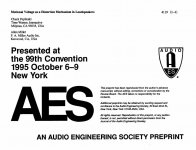
Motional Voltage as a Distortion Mechanism in Loudspeakers
An alternate model of the loudspeaker/amplifier system suggests a reason to prefer amplifiers with damping factors near unity. This analysis revolves around the motional voltage or back EMF generated by moving-coil loudspeakers. This model and some examples are presented and examined. A circuit which uses motional voltage feedback to synthesize a damping factor of unity is presented. While listening tests tend to show a preference for systems with unity damping, little support for this observation appears in the usual battery of tests. Analysis of these and other tests point to a combination of factors that makes low damping factors desirable.
Authors: Peplinski, Chuck; Miller, Allen
Affiliations: Time Warner, Interactive, Milpitas, CA ; F. A. Miller Audio Inc., Kenwood, CA,(See document for exact affiliation information.)
AES Convention:99 (October 1995) Paper Number:4119
Audio Amplifiers with Tailored Output Impedances
Discussed is an approach to amplifier design which appears to be suitable for use in driving loudspeakers whose frequency response characteristics tend to vary with their electrical impedance. The approach deals with tailoring amplifier output impedances to control loudspeaker behavior. The paper discusses some general rules of design and gives an example along with experimental tests. It concludes with the significance that such amplifiers can have on loudspeaker design and the potential for increased flexibility afforded the loudspeaker designer.
Author: Evenson, Roderick J.
Affiliation: Consulting Engineer, Milwaukie, OR
AES Convention:85 (November 1988) Paper Number:2693
Last edited:
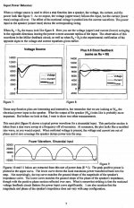
My idea would be to get the focus (this concept is explained in a post above) basing on the power signature signal following Peplinsky-Miller AES publication in 1995. See attached pictures.
Once you have your "flat" power signature in the time domain as described by Peplinsky-Miller (instantaneous current times instantaneous voltage) on a couple of frequency bandwidths (need a few banked bandpass filters - easy with DSP), and if you keep track of the value of the positive impedance you are generating for effectively attaining the unity damping factor, then you know everything about your load.
The algorithm to be used is the autofocus algorithm used in digicams. It starts hunting, but the more signal you give him as food (contrast and details), the more accurate and faster he gets in focus.
When you are in focus, it means thus that you have acquired with great precision the equivalent schematic of your loudspeaker in the closed box. Or, possibly, any other loudspeaker arrangement like a 4th order bass-reflex, 4th order bandpass, or 8th order bandpass aka Bose.
This is the way to automate the obtention of Peplinsky-Miller unity damping factor with a 0.1% precision, say from 10 Hz to 250 Hz.
This is my idea #1. Is this a new idea ?
What to do with the precise knowledge of the load impedance ?
Answer : sample the current using a small shunt resistor. Feed this current into analog components emulating the equivalent schematic, with the values you just calculated. Extract the pure motional voltage. It may be precise at 0.3 % if you use 12 bits DACs for defining the values of those analog components, if you use 0.1% precision resistances in your gyrators and capacitance multipliers, and if the target value are precise at 0.1% from the autofocus process described above.
I know it's a kind of rocket scientist solution for getting a high-precision wide bandwith motional voltage.
This is my idea #2. Is this a new idea ?
What to do with the motional voltage ?
Answer : use it into an outer feedback loop, encompassing all what got discussed untill here, for finally getting an inner unity damping factor arrangement, but completely motional voltage driven from the outside.
That is my idea #3. Is this a new idea ?
I don't expect to have the magnetics non-linearities corrected by such feedback. Philips MFB using an accelerator sensor does.
With time passing, this looks less and less like a rocket scientist solution, if one dares to call this a solution, nowadays.
A tiny SoC containing everything, including ADCs, DACs, DSP, laser-trimmed FET opamps, laser-trimmed resistors used in gyrators for synthezising the reactive components, will be cheaper, one day, than a PXE (piezo) crystal needing two terminals, one precision FET amp as buffer, and two or three supplementary wires and associated connector going to the driver.
If my 3 ideas are all right, all quality active loudspeakers will be built like this : a rocket scientist approach. With possibly more tricks for compensating the magnetics nonlinearities.
See attached pictures.
Steph
Attachments
Last edited:
I can remember the launch of the short lived servo sound loudspeaker in the seventies
I came across them in an exibition
I thought that they were really good for their size.
They in fact inspired me to produce some motional feed back spk of my own !
I fed the spk voice coil with an rf signal and had a pickup coil located in front! This amplitued modulated the signal so that I could determine the relative posistion of the cone and apply corrective feed back to put the cone where ir should be !
I was promised financial support by a then famous loudspeaker manufacturer to advance my ideas but whem push came to shove! they let me down and the project had to be dropped
regards Trev
seen here : http://electronicdesign.com/article...ansformer-winding-s-temperature-without-.aspx
May 26, 2009 11:44 AM
by Bill Whitlock
There's a much, much simpler way to monitor winding temperature. Simply include a winding that has an equal number of clockwise and counter-clockwise turns (hence, no AC output). If it is made of suitably small wire, it's easy to measure temperature using the well-known temp-co of copper. We do this in some of our transformers designed to be driven by amplifiers with negative output impedance.
Bill Whitlock, president & chief engineer
Jensen Transformers, Inc.
Chatsworth, CA, USA
www.jensen-transformers.com
My question : what if you replace the word "transformer" by the word "loudspeaker" ?
The aborted Grundig motional feedback system ? On some leaflets and pictures, some Grundig speakers had a "thing" facing the membrane, but I never managed to know what this was, actually. What you've done is wonderful ! You must be an RF specialist. Everybody else failed trying such an approach. Congratulation ! Can you tell us more about the practical results ? Signal / noise ratio was useable ? Do you still own the prototype ? Do you see obvious improvements to be made now, with the newest silicon ? Can we now replace the amplitude demodulation by triangulation using geometric wave processing ? Say a wavelenght of 5 cm for a max excursion to be 50% of the wavelenght. What is the complexity of a triangulation demodulator ? Would a passive metallized reflector suffice, glued on the center of the cone ? What signal / noise to expect using this approach ?Some motional feed back spk of my own : I fed the spk voice coil with an rf signal and had a pickup coil located in front. This amplitude modulated the signal so that I could determine the relative posistion of the cone and apply corrective feed back to put the cone where it should be.
Last edited:
Thanks for references. Things are coming into clearer focus for me.
Yes, this stuff is unstable and I doubt it can be made to work commercially or to work except in the experimenter's environment. Likewise, unfeasible except when you are working with a piston-like woofer from say, 200 Hz down, not trying PA sound levels, using good drivers, etc. But WOW, great woofing if you do.
Yes, some of the earlier demos (including my guide, Werner at RCA) acted as if the goal was getting big sound from tiny boxes. That's because MF can drive the speaker right down through resonance, whether the driver is willing or not. A worthy enough goal and with obvious commercial value if anybody can do it, but hardly the issue for us.
Yes, producing what is essentially a mirror-image (positive output impedance, if I am not confused too badly) of the speaker is the goal with bridge (or resistor or possibly a dedicated winding on the voice coil, as Whitlock and other in history have suggested) MF. The other systems of sensing speaker output (capacitive, accelerometer, mic) are fairly unfeasible feedback concepts and because they use the term "feedback" rather loosely.
Hate to seem anti-intellectual, but a basic issue is that you are messing about trying to make a simulation work. For example, fussing over coil temperature is not a real-world issue. As I said, perhaps too cryptically, if you can grab some feedback voltage, run with it.
Footnote: I recently became involved with Kenwood Basic M1 Amp with "Sigma Drive" - really remote sensing like with lab power supplies. Did you know this is really a motional feedback circuit, providing you have a long enough (resistant enough) line to the speaker? No kidding. Check it out. You can create the same circuit WITH ANY AMP by just taking your feedback from the speaker terminals the same way (instead of internal to the amp). The speaker leads are the sensor resistor or add .5 ohms.
Last edited:
Explanation for beginners
Whenever the voice coil moves too much or too little (hey, that's called distortion) it raises (or lowers) its back EMF. If you can sense that (across a resistor or better, across a bridge), you've got an error signal which can be fed back to the amp.
Below resonance in a sealed box, the speaker gets held back by air pressure and hence doesn't move as far as the amp output thinks it should. Therefore again, you get an error signal and the amp increases its effort to make the recalcitrant driver move more. Which is exactly what you want.
But for a bass-reflex cabinet, things are altogether different and MF is inapplicable.
Hello, I'm afraid we are not on the same wavelength yet.Yes, producing what is essentially a mirror-image (positive output impedance, if I am not confused too badly) of the speaker is the goal with bridge.
1. In this thread we are discussing about the control of a loudspeaker membrane without relying on a sensor. The aim is to have no accelerometer, no extra coil winding, no optical pickup, no RF system.
2. There is one post in this thread describing a very interesting RF system. This truly deserves a separate thread, as from what I'm understanding, there was a working prototype and maybe results or issues to be discussed on diyAudio.
3. The Servo-Sound ver.15B still needs to be properly reported. I can reverse-engineer the printed circuit. But I don't know what's inside the little black box next to the trimmer (see attached pictures).
4. The Servo-Sound ver.15B is sampling the current using a small resistor in series with the loudspeaker, and this signal seems to be used in a bridge substracting the I*R component from the overall voltage, hence coming close to the pure motional voltage.
5. If you do the maths, you'll see that point 4 is equivalent to feeding the loudspeaker using a negative resistance power source. Therefore, one can say that the Servo-Sound is a variant of the negative resistance power source. If the negative resistance is different in module from the actual coil copper resistance, the extraction of the pure motional voltage fails. It still contains a dumb (delta R * I) component. This is not a good start for organizing the feedback around it. But we can live with that.
6. More problematic, if the module of the negative resistance is greater than the actual coil copper resistance, you end up with a system that's fundamentally unstable.
Hate to seem anti-intellectual, but a basic issue is that you are messing about trying to make a simulation work. For example, fussing over coil temperature is not a real-world issue. As I said, perhaps too cryptically, if you can grab some feedback voltage, run with it.
Fundamentally I disagree with bentoronto. Point 5 above is indeed "grabbing some feedback voltage" with a planned inacurracy for ensuring that the module of the negative resistance is always smaller than the actual copper resistance. Back in 1957, Werner-Carell were right and prudents in limiting their ambitions in designing a negative resistance power source exhibiting 80% of the actual coil copper resistance. However, I think that the first generation Yamaha commercial AST amplifiers dating back from the early nineties (and associated personality modules) never dared to use such high percentage. Okay, Yamaha engineers job was no easy as the first generation Yamaha AST amps were separated and independents from the loudspeakers. And due to this, those AST amplifiers needed to be compatible with closed enclosures 2nd order, bass reflex 4th order, dual chamber 4th order, triple chamber 8th order aka Bose, transmission line, and so on.
7. One may say that the situation gets better if the amp is integrated in the box, like a closed box. Then we may use a 80% cancellation maybe. And yes, the results are fine. But at the end of the day you will lose your markets. Because a closed box approach is not the most efficient way to generate deep bass. Bass reflex 4th order, dual chamber 4th order and triple chamber 8th order aka Bose are more efficient, with less excursion for a given output level below 60 Hz. You can't ignore that the production cost of a loudspeaker driver is highly dependent of the max excursion he can deliver. You can't ignore that money matters in this world.
8. You may then want to try using the Servo-Sound principle on those other enclosures, and doing so you will need to put a frequency response amplitude and phase shaper in the feedback path. That's tricky. Then your colleage, boss or mentor seing your equalizer in the feeback path, and seing the risk that the wole system gets unstable if something goes wrong over there, will ALWAYS tell you "Hey, we are losing our time. This won't pass the consumer market test requirements. Let's drop this Servo-Sound idea. However, let us recycle it into a system that gets marketed as making a cancellation of the connecting wire resistance - about 0.5 ohm. This way our shareholders won't see we wasted R&D money and time".
9. Then, if you want to deeply extend the bass range, you will rely on a conventional pre-equalizer possibly tuned to the loudspeaker you are using, possibly equipped with a safe operating area module, containing a continuously variable high-pass filter, for avoiding overdriving the loudspeaker in the deep bass extension, at high levels.
10. This is all what will happen (and actually, happened) to people trying to follow or extend the Servo-Sound approach. Those are the consequences of applying the coarse idea of "if you can grab some feedback voltage, run with it". Personal opinion only, of course. See no offence to bentoronto. We are in a constructive debate.
What's the construction indeed ?
11. Well, the merge of two contradictory ideas. Starting from now we are not going to use a negative resistance power source. Instead we will use Peplinsky-Miller AES 1995 collateral finding about the "signature" of a system consisting on a loudspeaker connected on an amplifier having a POSITIVE resistance (or preferably, wideband impedance) EQUAL to the load it sees. There, on page 7 of Peplinsky-Miller AES 1995, you see the main clue of the collateral concept of "signature". Basing on the unity damping factor idea. Quite interesting findings they made, like there is less stress everywhere. Very sexy for the audiophile markets. And they have not used this concept in full. But in year 2010, we will. Let me show you.
12. Multiply the instantaneous current by the intantaneous voltage. If you are in focus, you get a particularity when you correlate this in a specific way with the input signal. This particularity enables to tell if you are in focus. Being "in focus" means that the wideband impedance of the power source is precisely equal (say max 0.1% error) to the load represented by the loudspeaker. You thus know everything about your equivalent schematic. You thus can extract the pure motional voltage. With a precison of 0.3% if you allow another 0.2% error in the rest of the circuit.
13. Then, if you want to drive the loudspeaker using the motional voltage, all you need is to put everything inside an outer feedback loop. Hoping it is stable.
Now everybody should be de-confused about negative and positive impedance power sources, and their use in the context of loudspeakers drive.
Please note that points 11, 12, 13 never been disclosed publicly, so I consider owning the paternity of this drive method (points 11, 12, 13 above) basing on Peplinsky-Miller AES 1995 collateral finding about the "signature" of a system consisting on a loudspeaker connected on an amplifier having a positive resistance (or preferably, wideband impedance) equal to the load it sees. Use it at your will, as I'm too old and too poor for dealing with patents and surrounding sharks and thieves. Who cares about audio and loudspeakers those days ? Seems we are the last Mohicans, here in diyAudio.
Steph
Attachments
Last edited:
A sealed box is a very good, safe, and clean way to make bass. Power is cheap and it is just a matter of feeding the speaker more power below system resonance esp. if you can have MF as your guide. I'm pretty hostile to tuned boxes even if you can configure the parameters to approximate an OK output curve and being "efficient" by surfing on two resonances with weird phases and amplitudes is not my idea of getting ahead of the game.
Rather presumptuous to talk about "losing markets" with a sealed box.
Even a little MF is a whole lot better than none.
It is inconceivable to make MF except when dedicated to one speaker system, not aiming for the last bit of perfection, and unless it was very very smart. I struggle to find words strong enough to convey my disparagement of the thought of a universal MF amp.
Yes, as I said yesterday, you want the output impedance of the amp to be mirror image of the speaker: 7 ohms when the speaker is 7 ohms and 2 ohms when the speaker is 2 ohms or someting like that. Is that roughly what Peplinsky says?
Yes, Werner talks about making the copper resistance disappear by using the bridge. Acutally just kind of arbitrary - in practice - what you are making disappear and hardly worth getting all too anxious about making the bridge too precisely to simulate the driver. Just grab some feedback, as I've been saying. If you were all-knowing about driver modeling in health and in distortion, you'd be able to build a perfect driver and not need MF.
A very interesting issue in MF is the ability to eat room modes, even if the woofer is not playing music at the time. I've never known enough tech stuff to look into it but a very intriguing "active absorber" idea, eh? Now there is a new idea.
Maybe you are saying something novel and different from what Werner didn't already say and try to patent for RCA. Remember, folks like RCA (or Bose, etc.) try to show that their "invention" is somehow curved differently than plain old obvious state of the art. Current feedback for loudspeakers goes back to the 40s.
Time to get a mic and do some real-world lab work and stop messing with models.
Last edited:
Yes, Werner talks about making the copper resistance disappear by using the bridge. Acutally just kind of arbitrary - in practice - what you are making disappear and hardly worth getting all too anxious about making the bridge too precisely to simulate the driver. Just grab some feedback, as I've been saying. If you were all-knowing about driver modeling in health and in distortion, you'd be able to build a perfect driver and not need MF.
Sorry to quote myself.
Even Werner, if I recall, added a capacitor here and there on the bridge to further emulate the speaker. Problem is that some of those elements you want to model are inherent driver features and some are The Problem you are trying to correct (and hence, you DON'T want to bridge them out of the feedback loop)... and not clear who is who.
And that is why I favor simple, mostly resistance-balanced, bridge-derived feedback.
The greatest progress of hifi has been the enlargement of feedback. MF is the last frontier of that loop by enclosing the speakers in the loop.
Always seemed odd to me that some much energy is lavished on minor issues of hifi in this forum while MF, with enormous benefits, has gotten little attention. Perhaps because it is a messy, cross-discipline area, including electronic, speaker acoustic, and room acoustic.
This might be of interest:
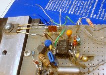
The first two pictures could give you some clues about the insides of "the black box": it is a thermal image shunt.
The following pixes illustrate a tentative electrostatic MFB speaker.
Despite its apparent crudeness, it probably deserves some more attention: preliminary tests showed an astonishingly good behavior and stability when enclosed in a relatively high-gain closed loop, without any precautions, calculations or compensation.
See you sometime on Futura
Attachments
Very interesting.
There are main routes to development (in my poor understanding).
One can aim for a piston-action driver (like the KEF B139 styrofoam eliptical woofer). Next, you must ensure the motion is linear with MF. Using the voice coil as a reference, you have 100 years of R&D are behind this approach.
Or you can measure the cone motion by using an accelerometer, position sensor of some kind (like capacitive/RF), photo, or otherwise, with or without smart processing. In as much as drivers have been carefully groomed for 100 years to have the smallest possible distortion, you need a sensor system that is better than the speaker or where the errors of the sensor are benign relative to the ear or the driver. The sensor has to have a range of about an inch. Where can I buy such a sensor cheap?
Otherwise, you might try acoustic feedback. But there are enormous obstacles to getting a mechanical, an acoustical, and an electronic system to work togther.
... and that's why I like the voice coil in a bridge concept.
2. You can
I like the idea of MF (and Steph's efforts in that direction) that I have one more thing to add... now that my aged memory is piqued.
When you push on an MF woofer cone, it kind of pushes back (sometime just feels rather solid like a wall and sometimes pushes back too much. It's ALIVE. A funny experience. Even had that experience with other woofers?
That is why I long-ago thought MF woofers would "eat" room resonances. Recently I read there's a patent on just such a concept. I wonder it is also eats room resonances while simultaneously making music? Wouldn't that be a cut-above passive woofers!
Again, I am implicitly making a distinction between fun experience of bench-top experimenting versus the dry (to me, at least) engineering approach.
Agree ! It was at the end of the eighties, 1988 or 1989 maybe. I remember taking our Philips RH541 MFB loudspeakers dating back from 1978, in a loudspeaker shop for comparing and buying new speakers like the newest Bose, B&W, Cabasse, Celestion, Dynaudio, JM Lab, JBL, KEF, Mission, Philips, Pierre-Etienne Léon, Sonus Faber, Sony, Wharfedale, Yamaha.That is why I long-ago thought MF woofers would "eat" room resonances. Recently I read there's a patent on just such a concept. I wonder it is also eats room resonances while simultaneously making music ?
After one hour comparison if was very clear that our Philips RH541 MFB loudspeakers were reproducing the human voice 10 times better than any other speakers. You could not find a speaker having a decent deep bass response, and still capable of accurate, realistic human voice reproduction. On all those conventional loudspeakers, bass was always in excess on the human voice, in a strange variable way. Hard to describe. The more we were listening, the more we had the conviction that the Philips RH541 MFB loudspeakers were taking control of the room, making it sound flat, less reverberant, and then, on such flattened and damped environment, delivering their audio signal. Even the owner of the shop was agreeing with us, about that.
We were fully aware that the Philips RH541 MFB were not perfect, with a high range being far from silk-smooth, provoking listening fatigue. Some speakers in this shop were vastly better than the Philips RH541 MFB, about smoothness in the high range, and we were agreeing with the shop owner about this. Globally, at the end of the process, we felt more comfortable with the Philips RH541 MFB listening experience, than with any other speaker that was in this shop.
We came back home without purchasing anything new. I remember the conversation with my dad, in the car upon coming back home. We developed the idea that the Philips RH541 MFB was eating the resonance modes of the listening room, as an undisclosed feature. We asked ourselves why Philips did not promoted that feature for marketing those loudspeakers. We concluded that it was maybe impossible to objectivate this feature.
Today in 2010 my parents are still listening to those same same Philips RH541 MFB loudspeakers. They are now connected on the TV set, where human voice reproduction accuracy matters.
In 1991, I bought Philips best available MFB loudspeakers, the F9638 models with flat cone woofer, flat cone medium, ribbon tweeter. It proved unreliable with problems with some connectors inside, and it was not featuring the impression that it was eating the resonance modes of the room. The sound delivered by the F9638 was dull. Less listening fatigue than the RH541, must say. Around year 2001, I couldn't cope with the reliability issues of the F9638 anymore, so I carefully dismantled them for re-using the transducers in a custom-made version. I dropped the project upon discovering that the flat woofer membrane was faked. Actually, it was the usual MFB woofer, now with a flat styrofoam plate glued on the front. Also, I got dissapointed when seeing how small was the excursion of the medium driver. I only kept the ribbon tweeters. I dumped the rest. I think that the F9638 was not eating the resonance mode of the room because of the faked flat membrane woofer. In such configuration, the accelerator sensor doesn't face the listening room anymore. There is that flat styrofoam membrane inbetween.
At the moment I own 4 or 5 MFB drivers type AD 7066/MFB
2422 257 47005
DD 00 946 126
packed as servicepart
4822 240 50099
Still waiting me to design something around.
I would appreciate if somebody points a link or posts information about the objectivation that some MFB speakers have the capability to eat the listening room resonance modes. Is there a patent about this, really ?
Cheers,
Steph
Last edited:
snip
I would appreciate if somebody points a link or posts information about the objectivation that some MFB speakers have the capability to eat the listening room resonance modes. Is there a patent about this, really ?
Cheers,
Steph
In MF (esp bridge type) the speaker is a mic too.
Is this relevant? It was kindly sent to me by a distinguished European poster.
Audio Engineering Society
Convention Paper 6520
Presented at the 118th Convention
2005 May 28–31 Barcelona, Spain
Active Acoustic Absorption and Reflection
Peter A. Swarte
P.A.S. Electro-acoustics,
Eindhoven, The Netherlands
e-mail: paswarte@cs.com
Abstract
The subject called "Active Absorption and Reflection" has already been theoretically discussed during one of the scientific sessions in 1986 of the Dutch Acoustical Society (NAG) in Delft, The Netherlands. The idea behind the subject was led down in a pending US patent. The patent has been granted to Philips in Dec.1987. The principle with the possible applications is described in publication nr 84 of the NAG d.d. April 1987.
Many others have investigated the phenomenon: a search on the Internet delivered in 2001 all publications of the Drittes Physikalisches Institut of the University of Göttingen, Germany. A lot of these publications had underwater
acoustics as application field. It was not an easy matter to give proof of the feasibility of the idea at that time. Nowadays, the technical possibilities
to do investigations and to gather convincing results have dramatically improved. With the help of adequate software implemented on a high quality personal computer and a special acoustical set up, the measurements can be performed in order to collect results that give a convincing support to the theoretical background. Two types of transducers i.c. a dynamic and an electrostatic (electret) transducer have been
investigated.
The transducers are an element of an electronic positive or a negative feed back circuit. The feed back circuit has to adapt the reflecting or absorbing nature of the diaphragms of the transducers to the desired degree of acoustic absorption or reflection. It is obvious that, at the same time, the transmitting properties of the diaphragms are also influenced. This phenomenon was in fact not a subject of this feasibility study. But a quick
investigation has shown that the transmission of sound is indeed influenced by the feed back control circuit.
In this feasibility study, the measurement set up and the results are explained and discussed. The results are encouraging. But this is only the beginning; a couple of investigations must be executed in order to
arrive at a manageable product. The products are expected to cover a wide range of acoustic and electro-acoustic applications.
Hello,
in may 1985, I was at the RTBF (radio television broadcast of belgian french communauty) as student in applied electronics. Everywhere, there were Philips MBF loudspeakers used : RH541, RH544 and RH545. So why ?
1) they used parts made in Belgium
2) the RH541 delivered an unbeatable quality/volume ratio in mobile use
3) the RH545 delivered the most consistent result with headphones, in control room use
One of the RTBF sound engineer took some time explaining me that the Philips RH545 was not the "best", but in reality "the only" system providing a nice consistency in a control room, not forcing you to reassess everything when you switch from headphones to free field (loudspeakers) and vice-versa, especially when balancing human voices.
The concept of the MFB "eating" the resonance modes of the listening room was thus not there, back in 1985.
I would like to know if the industry made some progresses in 25 years. Are there loudspeakers on the market, providing a better consistency than the Philips RH545, when switching from headphones to free field (loudspeakers) in a control room ?
P.S.
And thus, it is now clear why the Philips RH541 were so good at home and in a hifi shop on human voices (radio program listening) between 1980 and 1990. The RTBF sound engineer was balancing the sound, on his side, in the control room, using Philips MFB RH545 units, quite the same bass rendition as the Philips MFB RH541.
Cheers,
Steph
Last edited:
- Status
- This old topic is closed. If you want to reopen this topic, contact a moderator using the "Report Post" button.
- Home
- Amplifiers
- Solid State
- Servo-Sound made in Belgium